Liquid crystal display device

a technology of liquid crystal display and light source, which is applied in the direction of lighting device details, lighting and heating apparatus, instruments, etc., can solve the problems of slow light-up under low temperature and the like, unrealistic to expect a light-emitting diode module to have a lifetime equivalent to that of ccfl, etc., and achieve the effect of significantly reducing the life of the light-emitting diode modul

Inactive Publication Date: 2011-03-08
KYOCERA CORP
View PDF14 Cites 48 Cited by
  • Summary
  • Abstract
  • Description
  • Claims
  • Application Information

AI Technical Summary

Benefits of technology

[0018]The requirements that the light emitting diode module should satisfy include: having a replaceable structure; a prolonged lifetime by suppressing temperature increase; and being disposed at an optimum location with respect to the light incident surface of the light guide plate.
[0031]Moreover, since the present invention not only allows the light emitting diode module to be replaceable, but also allows heat generated from the light emitting diode module to be dissipated efficiently from the insulating substrate to the heat sink substrate, temperature increase in the light emitting diode module can be suppressed, and decrease in luminous efficiency can be restricted. As a result, a bright, long-life liquid crystal display device can also be realized.

Problems solved by technology

However, since this generates high frequency noise, not only noise prevention is additionally required, but also problems such as slow light-up under low temperature and the like are prone to arise.
The greatest problem here is lifetime of the light emitting diode module.
Because of many technical difficulties, it would be unrealistic to expect a light emitting diode module to have a lifetime equivalent to that of CCFL at this time.

Method used


Image

  • Liquid crystal display device
  • Liquid crystal display device
  • Liquid crystal display device

Examples


example

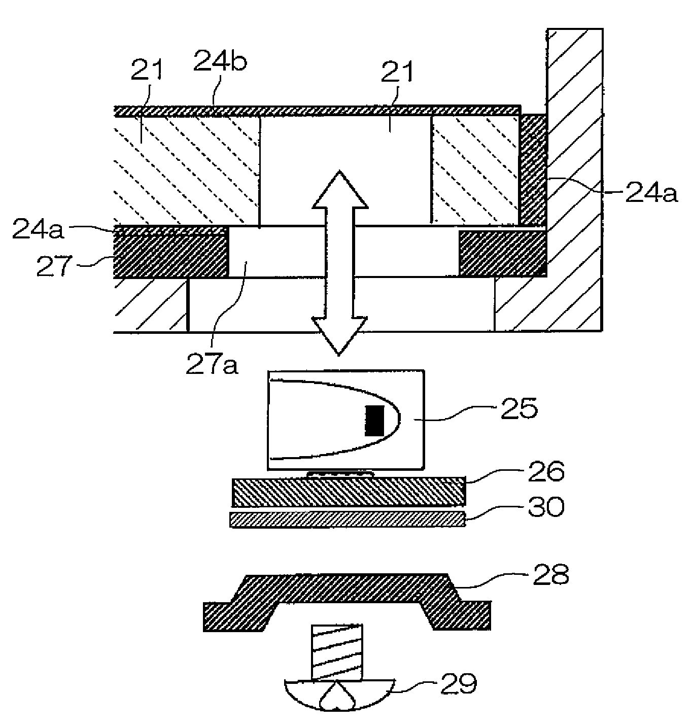
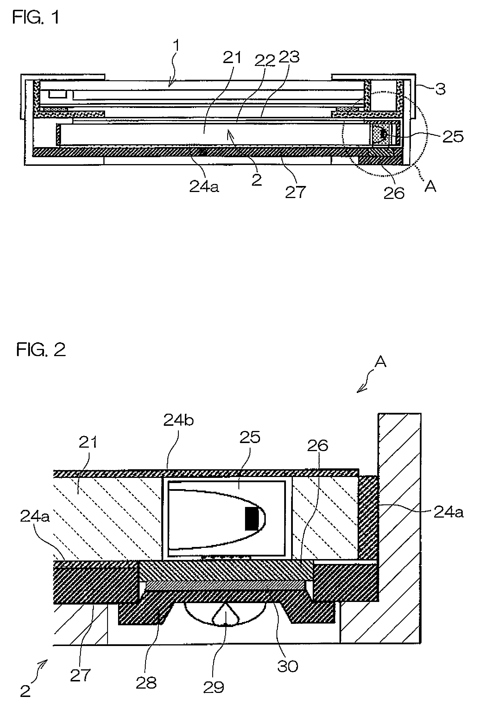
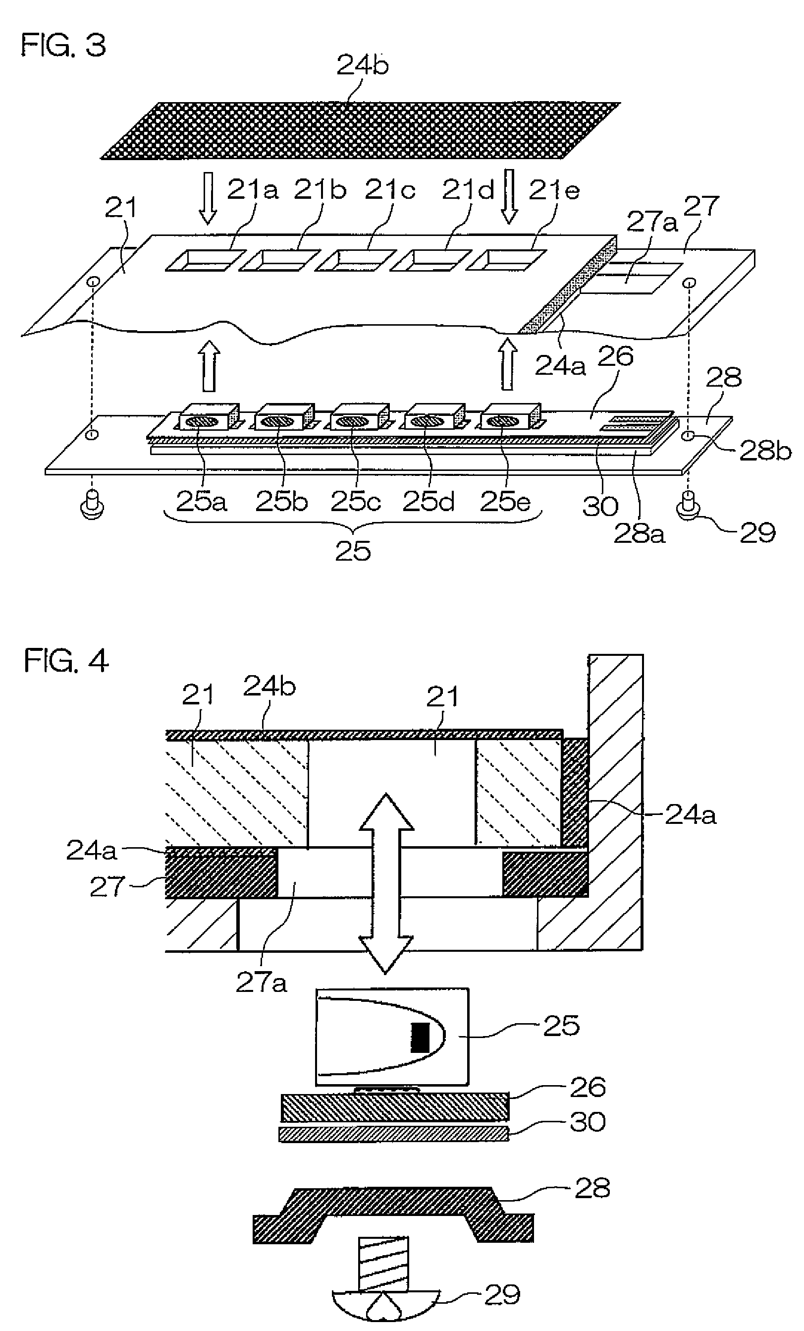
[0108]A 1.2 mm thick aluminum was used to form a heat sink substrate 27 and a metal holding plate 28, and a 0.125 mm thick thermoconductive adhesive tape, No. 8805 produced by Sumitomo 3M Limited, was used for a high-thermal-conductivity bonding material 30. The insulating substrate 26 and the metal holding plate 28 are bonded and fixed together by means of the bonding material 30, and the heat sink substrate 27 was secured to the metal holding plate 28 so that they were in surface contact with each other.

[0109]Here, the thermal conductivities of the materials used including glass epoxy for the insulating substrate, aluminum for the heat sink substrate and the holding plate, and thermal conductive adhesive tape for the high-thermal-conductivity bonding material were 0.45 W / m·K, 236 W / m·K and 0.6 W / m·K, respectively.

[0110]Heat generated with light emission of the LED light source 25 is propagated through the insulating substrate 26, the high-thermal-conductivity bonding material 30, ...


PUM

PropertyMeasurementUnit
temperatureaaaaaaaaaa

Abstract

The present invention relate to a liquid crystal display device using a light emitting diode (LED) module as a light source for backlight. Storing portions (21a-21e) are provided at positions facing a light emitting diode modules (25) on a light guide plate (21) constituting the backlight, and the light emitting diode modules (25) are inserted into the storing portions (21a-21e). Furthermore, under a status where an insulating substrate (26) mounted with the light emitting diode modules (25) is held by a holding plate (28), the holding plate (28) is removably attached to a heat sink substrate (27). The backlight has a structure wherein the light emitting diode module (25) can be replaced. Furthermore, since heat generated at the light emitting diode module (25) can be efficiently dissipated to the heat sink substrate (27), temperature increase of the light emitting diode module (25) is suppressed, and lifetime can be lengthened, and deterioration of luminous efficiency can be prevented.

Description

CROSS-REFERENCE TO THE RELATED APPLICATIONS[0001]This application is a National stage of international application No. PCT / JP2006 / 310711 filed May 30, 2006, which also claims benefit of priority under 35 U.S.C. §119 to Japanese patent application No. 2005-157084 filed May 30, 2005, the entire contents of which are incorporated by reference.TECHNICAL FIELD[0002]The present invention relates to a liquid crystal display device comprising a liquid crystal display panel and a backlight, and in particular, to a liquid crystal display device which utilizes a light emitting diode (LED) module as a light source for backlight.BACKGROUND ART[0003]Conventionally, transmissive-type and semi-transmissive-type liquid crystal display devices comprise a liquid crystal display panel and a backlight for supplying light transmitting to the liquid crystal panel.[0004]Generally, a backlight includes a light source and a light guide plate, and a small fluorescent tube called CCFL (cold cathode fluorescent...

Claims


Application Information

Patent Timeline
Patent Type & Authority Patents(United States)
IPC IPC(8): G02F1/1335G02F1/1333F21V7/04
CPCG02B6/0021G02B6/0068G02F1/133603G02F1/133608G02F2001/133628G02F1/133628
Inventor ABE, KAZUTOSHIIMAMURA, NAOYAKURAMOTO, SATOSHI
Owner KYOCERA CORP
Why Eureka
Try Eureka