Recursive filter system for a video signal

a filter system and video signal technology, applied in the field of recursive filter system for video signal, to achieve the effect of enhancing noise attenuation

Inactive Publication Date: 2011-03-08
TELEFON AB LM ERICSSON (PUBL)
View PDF18 Cites 4 Cited by
  • Summary
  • Abstract
  • Description
  • Claims
  • Application Information

AI Technical Summary

Benefits of technology

According to a second aspect of the invention, there is provided a method of enhancing noise attenuation in recursive filtering of a video image comprising the steps of: storing a first image to comprise stored picture elements S(x,y); generating a weighted value W(x,y) of luminance and chrominance of a stored picture element by summing weighted values B(x,y)·S(x,y) of luminance and chrominance of the picture element and neighbouring picture elements; generating a first proportional parameter A(x,y), for the stored picture element based on a sum of differences between the luminance and chrominance of the stored picture element and surrounding picture elements; using the first proportional parameter A(x,y) to generate a weighted picture element M(x,y) from a proportion A(x,y) of the stored picture element S(x,y) and a complementary proportion 1−A(x,y) of the weighted value W(x,y); inputting picture elements C(x,y) of a next image and a second proportional parameter K; using the second proportional parameter K to generate a filtered image by combining a proportion K of each input picture element C(x,y) of the next image with a complementary proportion 1−K of the weighted stored picture element M(x,y) of the first image; and storing the filtered image for corresponding combination with a succeeding image.

Problems solved by technology

While this technique in the feedback path in the recursive algorithm could cause localised softening to the image, any softening is confined to areas with noise, so producing more visually acceptable images

Method used


Image

  • Recursive filter system for a video signal
  • Recursive filter system for a video signal
  • Recursive filter system for a video signal

Examples


Embodiment Construction

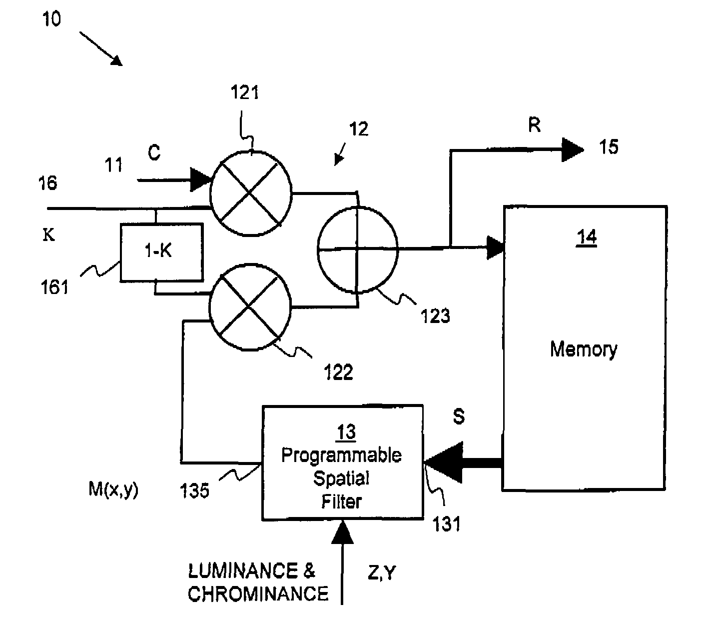
Throughout the description, identical reference numerals are used to identify like parts.

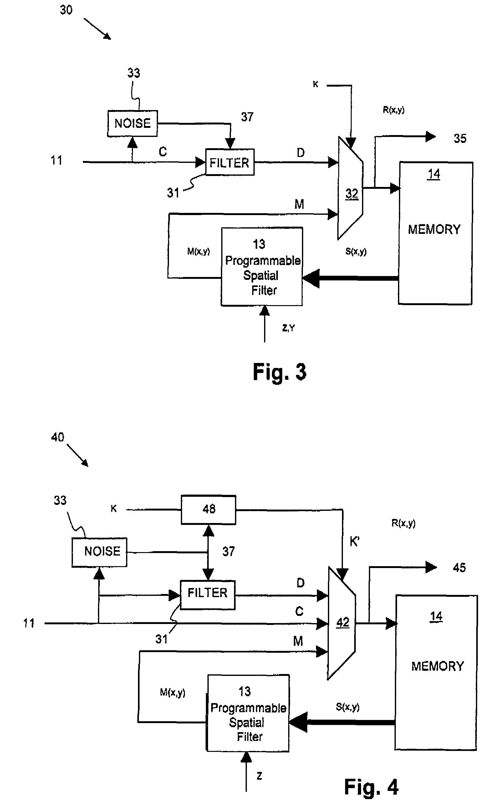
A simple application of the known prior art results in the pel field Rf(x,y) from Equation 1 containing more noise than necessary and can, by virtue of erroneous adaptation to perceived motion, contain large errors resulting from large noise signals such as those encountered in images that have been transferred from physical media such as acetate film.

To assist a description of the invention, Equation 1 above is recast as follows:

Rf(x,y)=K·Cf(x,y)+(1−K)·Mf−1(x,y)

0≦K≦1

Equation 2: Modified Recursive Noise Reduction Calculation

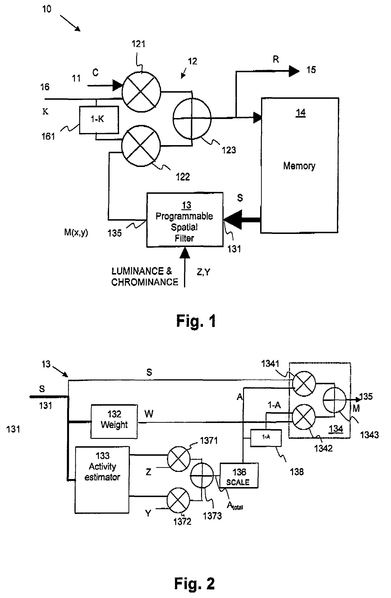
Where Mf−1(x,y) is the value of Rf(x,y) calculated for the previous frame and the index into the pel field is expressed as two-dimensional in order to clarify the derivation of a weighted average Wf(x,y) and Mf(x,y) given by:

Mf(x,y)=A·Sf(x,y)+(1−A)·Wf(x,y)

0≦A≦1

Equation 3: Calculation of the Historical Value M

Instead of using only the single spatially corresponding pel Sf(x,y)...


PUM


Abstract

A recursive filter system and method is provided. A weighted value of luminance and chrominance of a stored picture element is generated by summing weighted values of luminance and chrominance of a picture element and neighboring picture elements. A first proportional parameter for the stored picture element is generated with a sum of differences between the luminance and chrominance of the stored picture element and surrounding picture elements. A weighted picture element is generated from a proportion of the stored picture element and a complimentary proportion of the weighted value. Picture elements of the next image and a second proportional parameter are inputted. A filtered image is generated by combining a proportion of each input picture element of the next image with a complementary proportion of the weighted stored picture element of the first image. The filtered image is stored for corresponding combination with a succeeding image.

Description

FIELD OF THE INVENTIONThis invention relates to a recursive filter system for a video signal and in particular to localised diffusion to enhance noise attenuation in recursive filtering.BACKGROUND OF THE INVENTIONIt is known, from, for example BBC Research Department Report “Video noise reduction” BBC RD 1984 / 7 N. E. Tanton et al., July 1984, that random noise in a sequence of television images, or some other kinds of electronically generated images, e.g. scanned film, can be reduced by applying a recursive temporal filter which operates on each picture element hereinafter abbreviated to ‘pel’. It is beneficial to reduce noise levels prior to viewing images but it is also beneficial prior to processes that are sensitive to the presence of noise, especially compression systems such as those defined by, but not limited to, MPEG specifications. In practice, noise control is among several important and valuable techniques employed in pre-processing elements inherent in modern compressio...

Claims


Application Information

Patent Timeline
Patent Type & Authority Patents(United States)
IPC IPC(8): G06K9/40
CPCG06T5/002G06T5/20H04N19/85H04N19/14H04N19/182H04N19/80H04N19/117G06T2207/10016H04N5/21
Inventor MITCHELL, ARTHURHUGGETT, ANTHONY RICHARD
Owner TELEFON AB LM ERICSSON (PUBL)
Why Eureka
Try Eureka