

Fiber optic furcation assembly having feature(s) for cable management
a fiber optic furcation and fiber optic cable technology, applied in the direction of fibre mechanical structure, optical light guides, instruments, etc., can solve the problems of increasing cable congestion and heat per unit area, and increasing the number of fiber optic cable assemblies. sagging, affecting the service life of fiber optic cables, etc., to facilitate fiber optic interconnection, facilitate fiber optic cable management, and inhibit the sagging of fiber optic cable assemblies
- Summary
- Abstract
- Description
- Claims
- Application Information
AI Technical Summary
Benefits of technology
Problems solved by technology
Method used
Image

Examples
Embodiment Construction
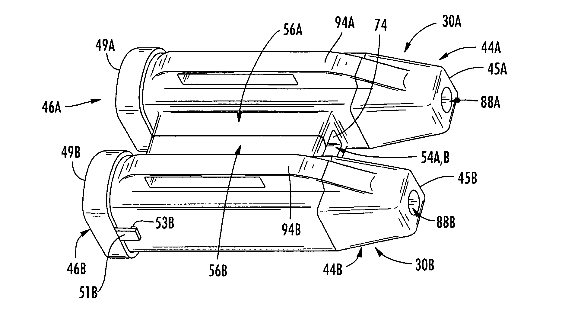
[0011]Embodiments disclosed in the detailed description include fiber optic cable assemblies having a fiber optic cable, a furcation body, and one or more furcated legs. In embodiments disclosed herein, the furcation body comprises a first end and a second end opposite the first end, the first end having the fiber optic cable extending therefrom, and the second end having one or more furcated legs extending therefrom. The furcation body can include one or more features that facilitate fiber optic cable management. These disclosed features of fiber optic cable assemblies may advantageously inhibit fiber optic cable assemblies from sagging (i.e., provide support), facilitate access to fiber optic interconnections, prevent or reduce obstruction of air flow paths between fiber optic interconnections, and / or inhibit tangling among fiber optic assemblies.
[0012]Additional features and advantages will be set forth in the detailed description which follows, and in part will be readily appare...
PUM
 Abstract
Description
Claims
Application Information