Multi-engine aircraft

a multi-engine aircraft and engine technology, applied in the direction of lighter-than-air aircraft, power plant exhaust arrangements, transportation and packaging, etc., can solve the problems of increasing the mass of the third engine, increasing the noise generated by the engine, and generating considerable noise, so as to reduce the previous acoustic problems, less heavy, and less noisy

Inactive Publication Date: 2011-03-15
AIRBUS OPERATIONS (SAS)
View PDF24 Cites 51 Cited by
  • Summary
  • Abstract
  • Description
  • Claims
  • Application Information

AI Technical Summary

Benefits of technology

[0008]Thus, by virtue of the invention, the design of the rear tail sections and the arrangement of the third engine at the inlet of the channel makes it possible to considerably reduce the previous acoustic problems, since the noise generated by the third engine of the fuselage is sucked up by the channel so as to be discharged along the latter and upwardly away from the fuselage, that is to say away from passengers situated in the rear of the cabin and a fortiori away from residents living near airports. The noise generated is thus masked by the rear tail sections of the fuselage, which constitute an acoustic shield.
[0009]Consequently, since the invention partially overcomes the problems connected with noise nuisance, it is possible to return to a three-engine construction and thus design aircraft advantageously equipped with wing engines which are dimensionally smaller, and therefore less heavy and less noisy, while retaining an overall power which is analogous to a twin-jet aircraft equipped with large engines.

Problems solved by technology

These aircraft, the design of which dates back to the 1970s, and some of which are still in service, are equipped with powerful engines to provide long-haul services; however, given the era in which they were designed, these engines generate considerable noise and entail a high fuel consumption.
Specifically, the noise generated by the third engine is particularly disturbing to passengers situated in the rear of the cabin, and also to residents living near airports when the aircraft is in the landing or takeoff phase, since the placement of this third engine means that the noise is diffused all around the aft portion of the fuselage.
However, on the other hand, these powerful turbofans have an ever-increasing mass and size, thereby making it necessary for the aircraft structure (fuselage, wings and landing gear in particular) to be designed accordingly so that it can withstand the stresses, and, by virtue of their oversizing, said jet engines also generate a significant noise level both for passengers and residents living near airports (in the takeoff and landing phase), this in spite of the advances made in this field by engine manufacturers.

Method used


Image

  • Multi-engine aircraft
  • Multi-engine aircraft
  • Multi-engine aircraft

Examples


Embodiment Construction

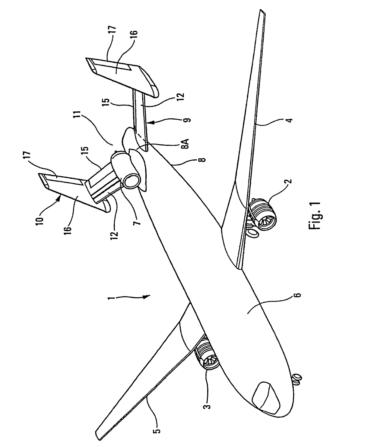
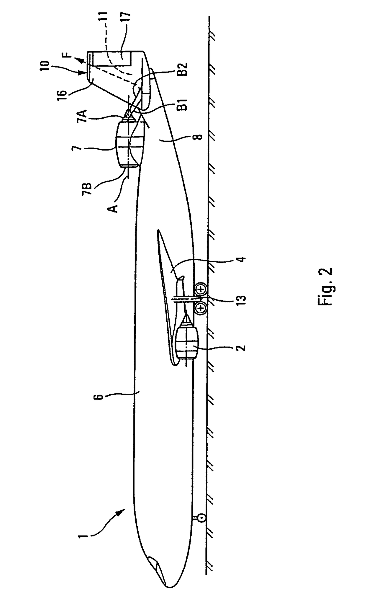
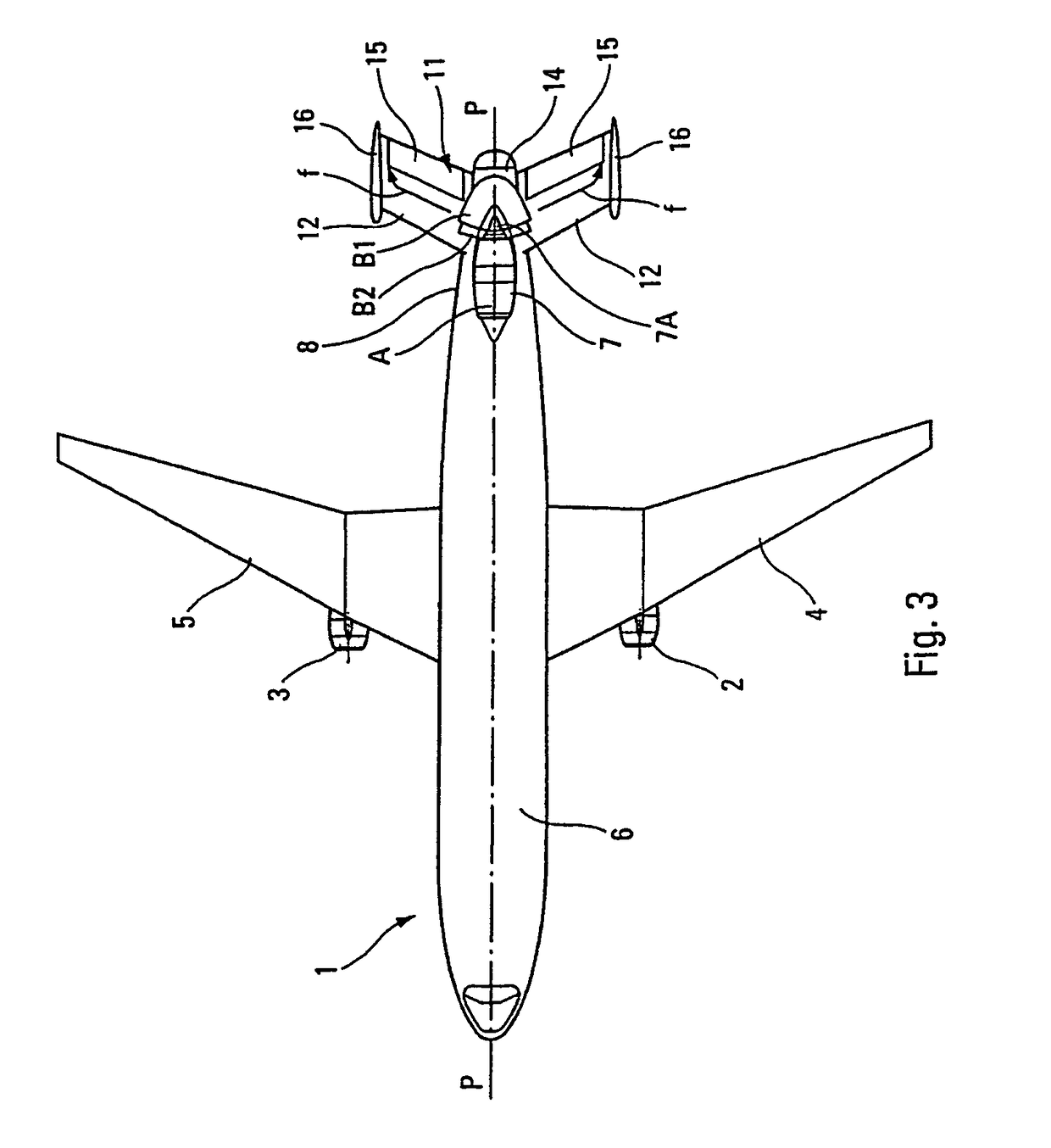
[0022]In the exemplary embodiment represented in FIGS. 1 to 4, the aircraft 1 comprises three engines (of the turbofan type), two 2, 3 of which are arranged below the wings 4, 5 of the fuselage 6, respectively, symmetrically with respect to the vertical longitudinal plane of symmetry P of said fuselage, and the third 7 of which is provided at the rear part 8 of the fuselage, containing the horizontal and vertical rear tail sections 9 and 10, along the longitudinal plane P. The reference number 13 represents the customary landing gear of such an aircraft.

[0023]As is shown more specifically in FIGS. 1, 4 and 5, the horizontal 9 and vertical 10 tail sections define, according to the invention, a channel 11 which is, in this example, approximately U-shaped and which is geometrically symmetrical with respect to the longitudinal plane P of the fuselage 6. The third engine 7 is then arranged in the plane of symmetry of the channel, that is to say the plane P, and is advantageously arranged...


PUM


Abstract

A multi-engine aircraft includes at least two first engines and a third engine located at a rear part of the fuselage, containing rear tail sections, along a vertical longitudinal plane of symmetry of the fuselage. The rear tail sections define a channel which is symmetrical with respect to the longitudinal plane of the fuselage. The third engine is arranged in the plane of symmetry of the channel corresponding to the longitudinal plane and is mounted on the upper part of the fuselage in a raised manner and in front of the tail sections, so that the outlet of the third engine is situated substantially at the inlet of the channel defined by the tail sections.

Description

FIELD OF THE INVENTION[0001]The present invention relates to a multi-engine aircraft and more specifically, although not exclusively, to an aircraft equipped with three engines, two of which are joined respectively to the fuselage wings symmetrically with respect to the vertical longitudinal plane of said fuselage and the third of which is provided in the rear part of the fuselage in the region of the rear tail sections.BACKGROUND OF THE RELATED ART[0002]Aircraft equipped with three engines and having the construction summarized above, such as the LOCKHEED L1011 and the McDONNELL DOUGLAS DC-10 or MD-11, are already known. In particular, the third engine is situated, structurally and geometrically, between the horizontal tail section and the vertical tail section and carries the fin of said vertical tail section. These aircraft, the design of which dates back to the 1970s, and some of which are still in service, are equipped with powerful engines to provide long-haul services; howeve...

Claims


Application Information

Patent Timeline
Patent Type & Authority Patents(United States)
IPC IPC(8): B64D27/00B64D27/20B64D27/26B64D33/04
CPCB64C5/06B64D27/20Y02T50/44Y02T50/40
Inventor CAZALS, OLIVIERGENTY DE LA SAGNE, JAIMERITTINGHAUS, DENIS
Owner AIRBUS OPERATIONS (SAS)
Why Eureka
Try Eureka