Injection system having readable information stores and method for controlling the operation thereof

a technology of information storage and injection system, which is applied in the field of fluid delivery system, can solve the problems of high flow rate and high pressur

Inactive Publication Date: 2011-03-15
BAYER HEALTHCARE LLC
View PDF35 Cites 63 Cited by
  • Summary
  • Abstract
  • Description
  • Claims
  • Application Information

AI Technical Summary

Benefits of technology

[0010]In general, the continuous pumping mechanisms of the present invention enable convenient operation via continuous (or uninterrupted) pumping of fluid from the container (without, for example, having to stop and reload) over multiple procedures and / or patients. Moreover, a patient dose can be determined in real time as the procedure is progressing, ensuring that the patient will be neither over dosed nor under dosed. Moreover, no waste of fluids occurs as a result of over dosing or under dosing.
[0013]Preferably, continuous pumping mechanisms for use in the present invention provide for relatively accurate control of a bolus of fluid delivered to a patient (for example, rise and fall times of under 100 ms can be provided in the case of, for example, a square bolus). A square bolus of fluid delivery or other bolus configuration may be required for optimum enhancement.
[0015]The fluid delivery system of the present invention can further include at least one one-way valve or other mechanism in fluid connection with the container (for example, between the pumping mechanism and the container) to prevent flow of fluids from outside the container into the container (for example, from the pumping mechanism into the container). In one embodiment, the container includes a plurality of ports in fluid connection with the pumping mechanism, and a one way valve is in fluid connection between the pumping mechanism and each the plurality of ports, to prevent flow from the pumping mechanism to the container. Preventing flow of fluid from outside of the container into the container (for example, from the pumping mechanism to the container) can reduce the likelihood of cross-contamination between patients when the fluid delivery systems of the present invention are used in connection with multiple patients. Likewise, undesirable fluids (for example, air or, indeed, any fluid other than the original contents of the container can be prevented from entering the container. Additionally or alternatively, the pumping mechanism is adapted (for example, via means known in the pumping arts) so that it cannot pump fluid from outside the container into the container. In other words, the pumping mechanism cannot be operated in reverse. Preventing such reverse flow can further reduce or eliminate the likelihood of cross-contamination between patients and reduce the likelihood of drawing fluids (for example, air) into the container. Preferably, continuous pumping mechanisms used in the present invention facilitate generally the prevention of or the minimization of delivery of air to a patient during an injection procedure.
[0020]In one embodiment, the container comprises no inlet port through which a fluid can enter the container. In this manner, contamination of fluid within the container with external agents can more easily be prevented. However, such inlet ports can be provided in certain embodiments. The fluid container and the pumping mechanism of the fluid delivery systems of the present invention can, for example, be disposable as unit.
[0024]Each of the pressurizing chambers can be in fluid connection with a single pumping mechanism outlet. In one embodiment, the pressurizing chambers are formed from a flexible, resilient material that can be compressed to pressurize fluid within the pressurizing chamber. The flexible material of the pressurizing chambers can be suitably resilient such that recovery of the flexible material of the pressurizing chambers creates a pressure difference between the pressurizing chamber and the storage container suitable to draw fluid from the storage container into the pressurizing chambers. The drive mechanism can include at least one drive member to compress the pressurizing chambers. The drive mechanism can, for example, include a drive member for each of the pressurizing chambers to compress each of the pressurizing chambers in a timed fashion. The operation of the drive member can be appropriately timed to reduce pulsatile nature of the flow.

Problems solved by technology

Typically, high flow rates are associated with high pressures as a result of delivery of such high flow rates through relatively small-bore flow path elements (for example, catheters).

Method used


Image

  • Injection system having readable information stores and method for controlling the operation thereof
  • Injection system having readable information stores and method for controlling the operation thereof
  • Injection system having readable information stores and method for controlling the operation thereof

Examples


Embodiment Construction

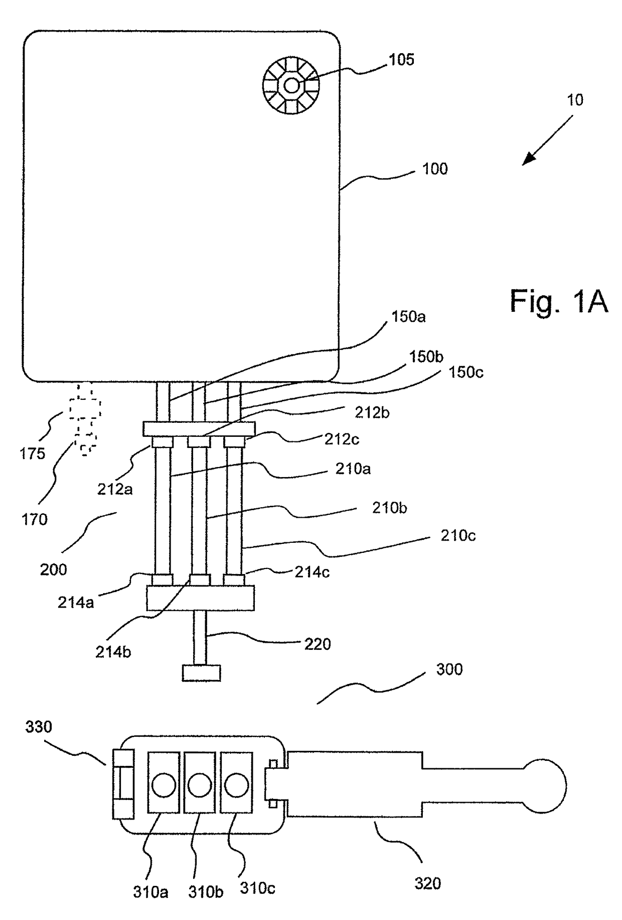
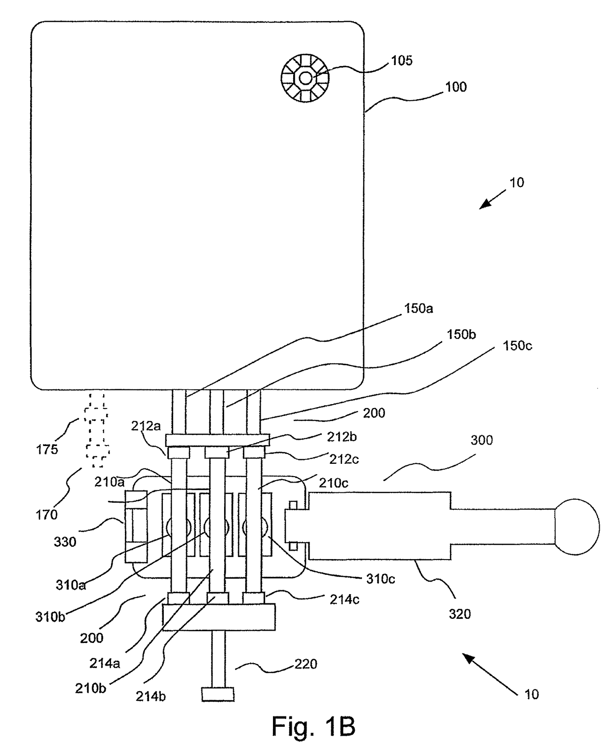
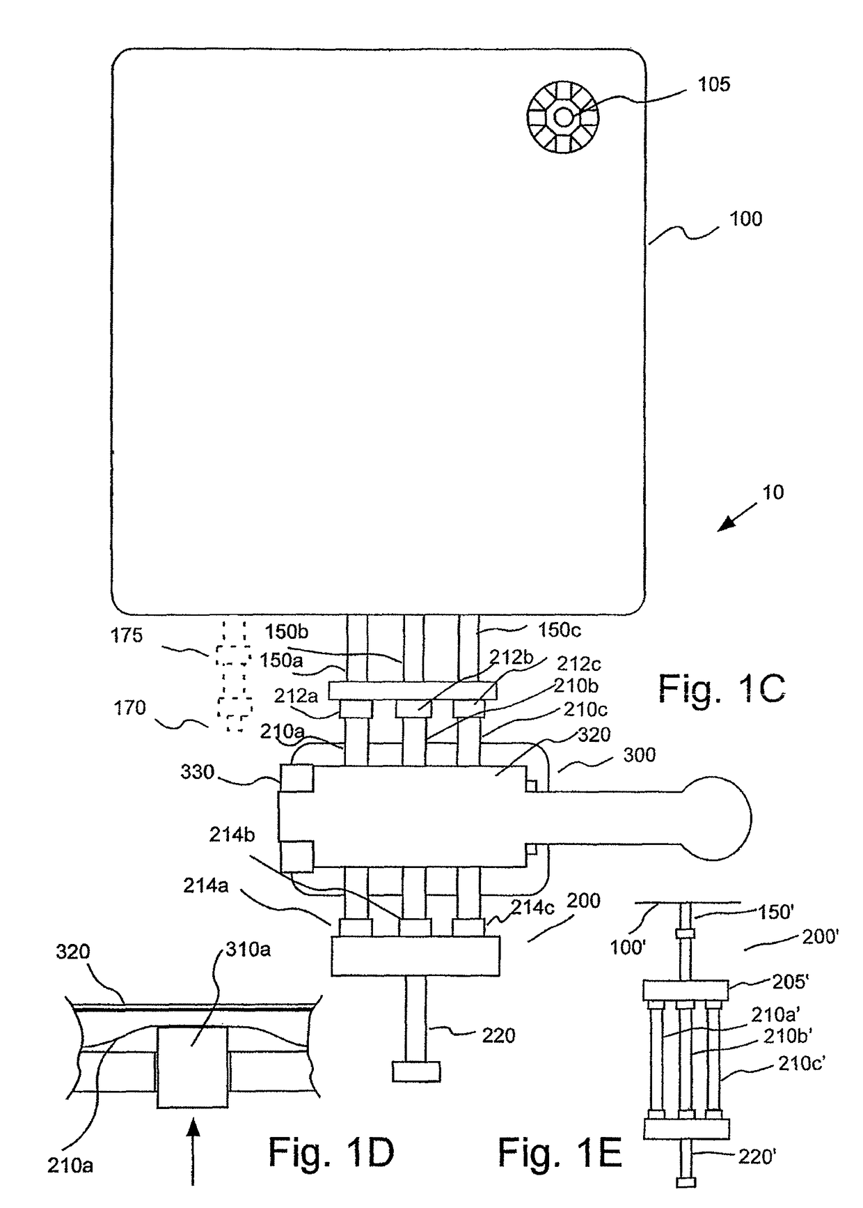
[0055]In general, the present invention provides fluid delivery systems that can be used to inject one or more fluids into one or more patients. FIGS. 1A through 1D illustrate an embodiment of a fluid delivery system 10 of the present invention in which a fluid container 100 is in operative connection with a continuous pumping mechanism 200 including multiple pressurizing chambers. In the embodiment of FIGS. 1A through 1C, pumping mechanism 200 includes three pressurizing chambers 210a, 210b and 210c. System 10 further includes an actuator or drive mechanism 300, which operates in connection with pumping mechanism 200 to pump fluid from within fluid container 100.

[0056]In one embodiment, each of pressurizing chambers 210a, 210b and 210c is formed from a flexible, resilient material such as a resilient polymeric material (for example, silicone polymer materials, urethane polymer materials and vinyl polymer materials). Drive mechanism 300 includes drive members 310a, 310b and 310c, wh...


PUM


Abstract

An injection system includes a fluid delivery system, a drive mechanism, a controller and a tubing set. The fluid delivery system includes a fluid container and a pumping mechanism having an inlet in fluid connection with the fluid container and an outlet. The tubing set is adapted to be placed in removable fluid connection with the outlet of the pumping mechanism and a patient. The drive mechanism is in operative connection with the pumping mechanism to pump fluid from the fluid container. First and second information stores, such as bar codes or RFID tags, are associated with the pumping mechanism and the tubing set, respectively. The controller is in operative connection with the drive mechanism and adapted to read the first information store and the second information store to at least partly control the operation of the drive mechanism based thereon.

Description

CROSS REFERENCE TO RELATED APPLICATION[0001]This application is a continuation of U.S. patent application Ser. No. 11 / 072,999, filed on Mar. 4, 2005, now abandoned, the contents of which are incorporated herein by reference.BACKGROUND OF THE INVENTION[0002]The present invention relates generally to fluid delivery systems, to fluid delivery devices and to methods of fluid delivery, and, especially, to fluid delivery systems, devices and method for delivery of medical fluids to a patient.[0003]In many medical procedures, such as drug delivery, it is desirable to inject a fluid into a patient. Likewise, numerous types of contrast media (often referred to simply as contrast) are injected into a patient for many diagnostic and therapeutic imaging procedures. For example, contrast media are used in diagnostic procedures such as X-ray procedures (including, for example, angiography, venography and urography), computed tomography (CT) scanning, magnetic resonance imaging (MRI), and ultrason...

Claims


Application Information

Patent Timeline
Patent Type & Authority Patents(United States)
IPC IPC(8): A61M1/00
CPCA61M5/1422A61M5/007A61M2206/22A61M5/002A61M2205/128A61M5/16827A61M5/16881
Inventor RHINEHART, EDWARD J.HACK, DENNIS P.REILLY, DAVID M.KALAFUT, JOHN F.
Owner BAYER HEALTHCARE LLC
Why Eureka
Try Eureka