Method and apparatus of measuring beam current waveforms

a beam current waveform and waveform technology, applied in the field of beam current waveform measurement methods and apparatuses, can solve the problems of reducing the life span of the switch, wasting time, and wasting resources, and achieve the effect of high precision

Active Publication Date: 2011-03-22
NISSIN ION EQUIP CO LTD
View PDF16 Cites 0 Cited by
  • Summary
  • Abstract
  • Description
  • Claims
  • Application Information

AI Technical Summary

Benefits of technology

[0018]One or more embodiments of the present invention provide a measurement method and apparatus capable of measuring the waveforms of beam currents flowing into a plurality of beam detectors of a beam monitor having the beam detectors using a small number of current measurement apparatus for a short period of time with high precision.

Problems solved by technology

However, since the switches S of the beam detectors 32 are sequentially switched on one by one so as to measure the beam current waveforms, the measurement is time-consuming.
Although the switches S are switched at a high speed, since a standby time due to switching delay times of the switches S or a response delay time of the current measurement apparatus 40 is required, there is a speed-up limitation.
In addition, the life spans of the switches S may be reduced or reliability of connection may deteriorate.
However, since the current measurement apparatus 40 is respectively provided in the beam detectors 32, it is difficult to equalize the measurement precision of the current measurement apparatus 40.

Method used


Image

  • Method and apparatus of measuring beam current waveforms
  • Method and apparatus of measuring beam current waveforms
  • Method and apparatus of measuring beam current waveforms

Examples


Embodiment Construction

[0046]FIG. 5 is a view showing an example of a measurement apparatus for performing a measurement method of beam current waveforms according to an exemplary embodiment of the invention. The same or similar portions as the conventional example shown in FIGS. 2 and 3 are designated by like reference numerals and a difference between the conventional example and the embodiment of the invention will be mainly described.

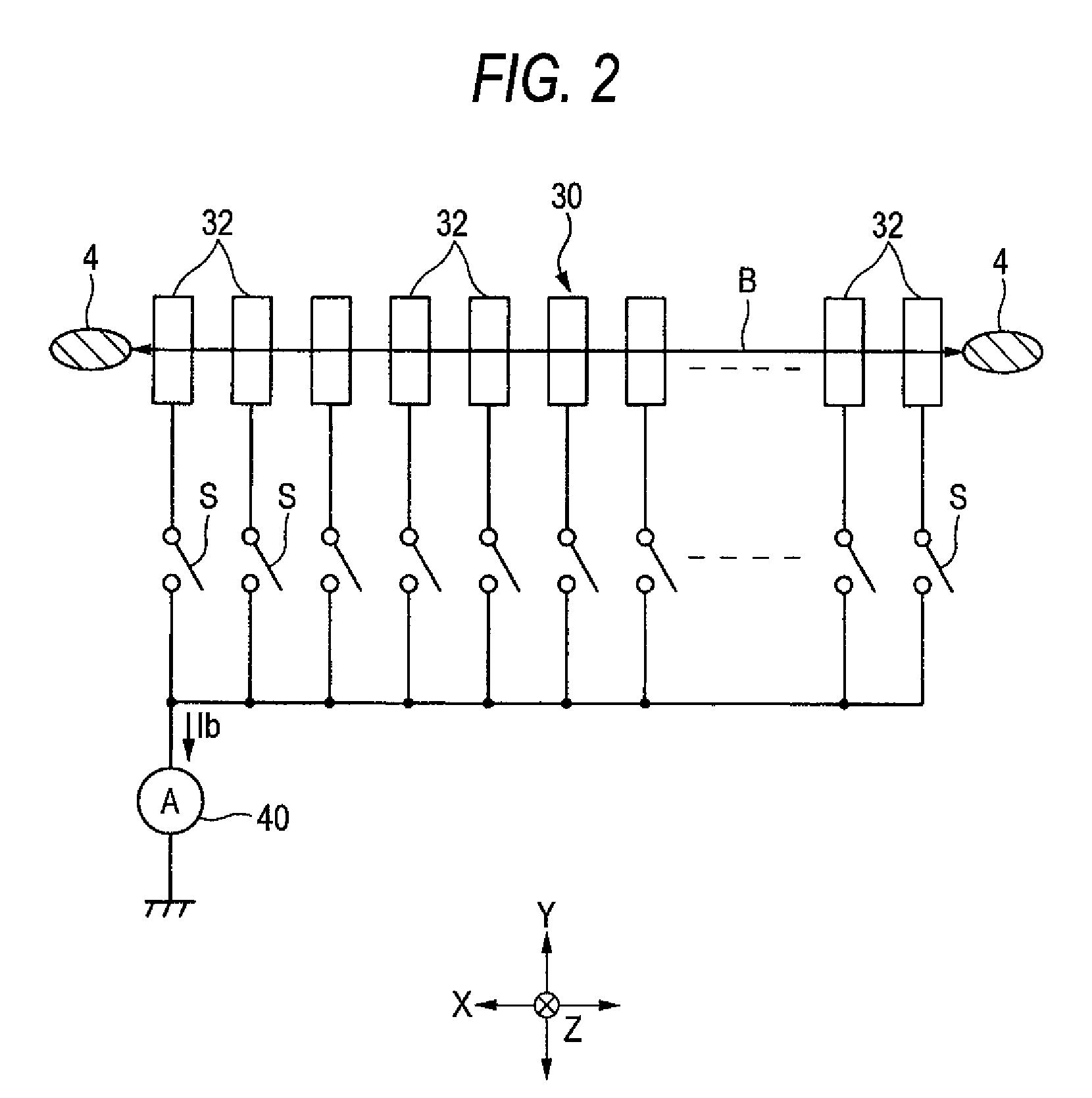
[0047]In the following, in order to readily specify a switch S, the total number of beam detectors 32 configuring a beam monitor 30 is set to 16 (that is, p=16) and the switches S respectively connected to the beam detectors 32 are designated by reference numerals S1 to S16 from one end of the X direction. However, the number of the beam detectors is not limited to 16. When the position of the switch is not specified, the switch is only designated by the reference numeral S. The same is true even in a measurement apparatus 60b shown in FIG. 9.

[0048]In a measurement appara...


PUM


Abstract

Beam detectors configuring a beam monitor are connected to a single current measurement apparatus through respective switches. If a width of a beam incident hole of each of the beam detectors 32 in the X direction is Wf, a gap between the beam incident holes of adjacent beam detectors in the X direction is Ws, a beam width of the ion beam in the X direction is Wb, a total number of beam detectors is “p”, and “n” is an integer of 0≦n≦(p−2) and satisfying Wb<{n·Wf+(n+1)Ws}, a measuring process of receiving the ion beam by the beam monitor and measuring the waveforms of the beam currents flowing into the current measurement apparatus in a state in which the plurality of switches skipped by “n” are simultaneously switched ON and a switching process of switching the switches simultaneously switched ON under the condition, are repeated.

Description

[0001]The present invention claims priority from Japanese Patent Application No. 2007-011360 filed on Jan 22, 2007, the entire content of which is incorporated herein by reference.BACKGROUND OF INVENTION[0002]1. Field of the Invention[0003]The present invention relates to a measurement method and apparatus which are, for example, used in an ion implantation apparatus, for receiving ion beam scanned in an X direction and measuring the waveforms of beam currents flowing into a plurality of beam detectors in a beam monitor in which the plurality of beam detectors are arranged at the same interval in the X direction (for example, a horizontal direction, the same applies to the following).[0004]2. Description of the Related Art[0005]FIG. 1 is a schematic plan view showing an example of an ion implantation apparatus. This ion implantation apparatus includes an ion source 2 for emitting ion beam 4, a mass separator 6 for receiving the ion beam from the ion source 2 and separating and takin...

Claims


Application Information

Patent Timeline
Patent Type & Authority Patents(United States)
IPC IPC(8): G21K5/10
CPCH01J37/244H01J37/304H01J37/3171H01J2237/2446H01J2237/24542H01J2237/30472
Inventor KOBAYASHI, TOMOAKI
Owner NISSIN ION EQUIP CO LTD
Why Eureka
Try Eureka