MEMS device with tandem flux concentrators and method of modulating flux

a technology of flux concentrator and magnetic field, applied in the field of sensors, can solve the problems of sensitivity, power consumption, cost, etc., and achieve the effects of minimizing 1/f noise, improving sensitivity of magnetic sensor operation, and minimizing 1/f nois

Inactive Publication Date: 2011-03-29
ARMY US SEC THE THE
View PDF9 Cites 17 Cited by
  • Summary
  • Abstract
  • Description
  • Claims
  • Application Information

AI Technical Summary

Benefits of technology

[0029]Improved sensitivity of magnetic sensors operating at low frequencies is achieved by using flux concentrators that modulate an observed or sensed magnetic field, thereby shifting this observed field to higher frequencies where the noise of the sensor is smaller to minimize 1 / f-type noise. A high resonant frequency is desirable in order to operate at higher frequencies where 1 / f noise is small. In accordance with the principles of the present invention, a microelectromechanical modulating device comprises a pair of magnetic flux concentrators, as shown for example in FIGS. 5-7, that may move in tandem. In combination with a magnetic sensor, the magnetic field is modulated to minimize 1 / f noise.
[0031]A preferred embodiment of the present invention provides a magnetic sensor assembly with an optional extended or supplemental flux concentrator that enhances the input of flux. The supplemental flux concentrator has a mass independent of the movable flux concentrators. The supplemental flux concentrator enhances the ability of the flux concentrators to receive flux without affecting the frequency of the movable flux concentrators. A preferred embodiment may also incorporate vacuum packaging to reduce frictional resistance imparted by the air. A preferred embodiment assembly can be produced, for example, by microfabrication MEMS-techniques, producing a small and inexpensive yet extremely sensitive magnetic sensor. The magnetic sensor can be a Hall effect or other type of magnetic sensor. The MEMS flux concentrators 40 may be composed of a soft magnetic material, such as permalloy, deposited on MEMS structures.

Problems solved by technology

For example, for automotive and high volume applications the prime factor is cost.
For use in unattended ground sensor networks the prime factors are cost, sensitivity, power consumption, and visibility.

Method used


Image

  • MEMS device with tandem flux concentrators and method of modulating flux
  • MEMS device with tandem flux concentrators and method of modulating flux
  • MEMS device with tandem flux concentrators and method of modulating flux

Examples


Embodiment Construction

re magnified over 10 times.

[0053]FIG. 17A is a view of the MEMS structure in motion.

[0054]FIG. 17 B is the frequency dependence of the amplitude of the device showing the two in-plane normal modes.

[0055]FIG. 17C is an illustration of the electrical comb 11 showing the overlap of the teeth used to transfer the ac driving current.

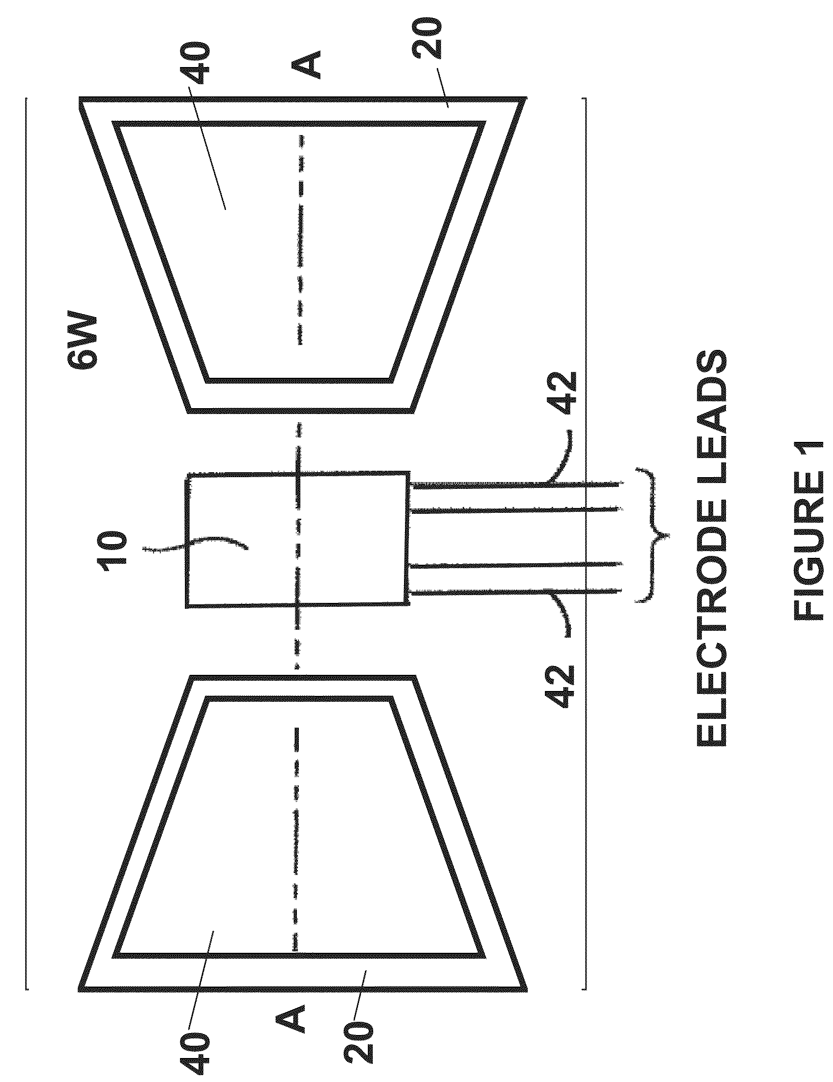
[0056]FIG. 18 illustrates a perspective view of the flux concentrators.

[0057]FIG. 19 illustrates an alternative embodiment of the present invention having a movable alternate flux path comprising soft magnets 48 supported by spring(s) 50S.

[0058]FIG. 20 illustrates an alternative embodiment of the present invention having a movable alternate flux path comprising soft magnets 48 supported by a lever subassembly 54.

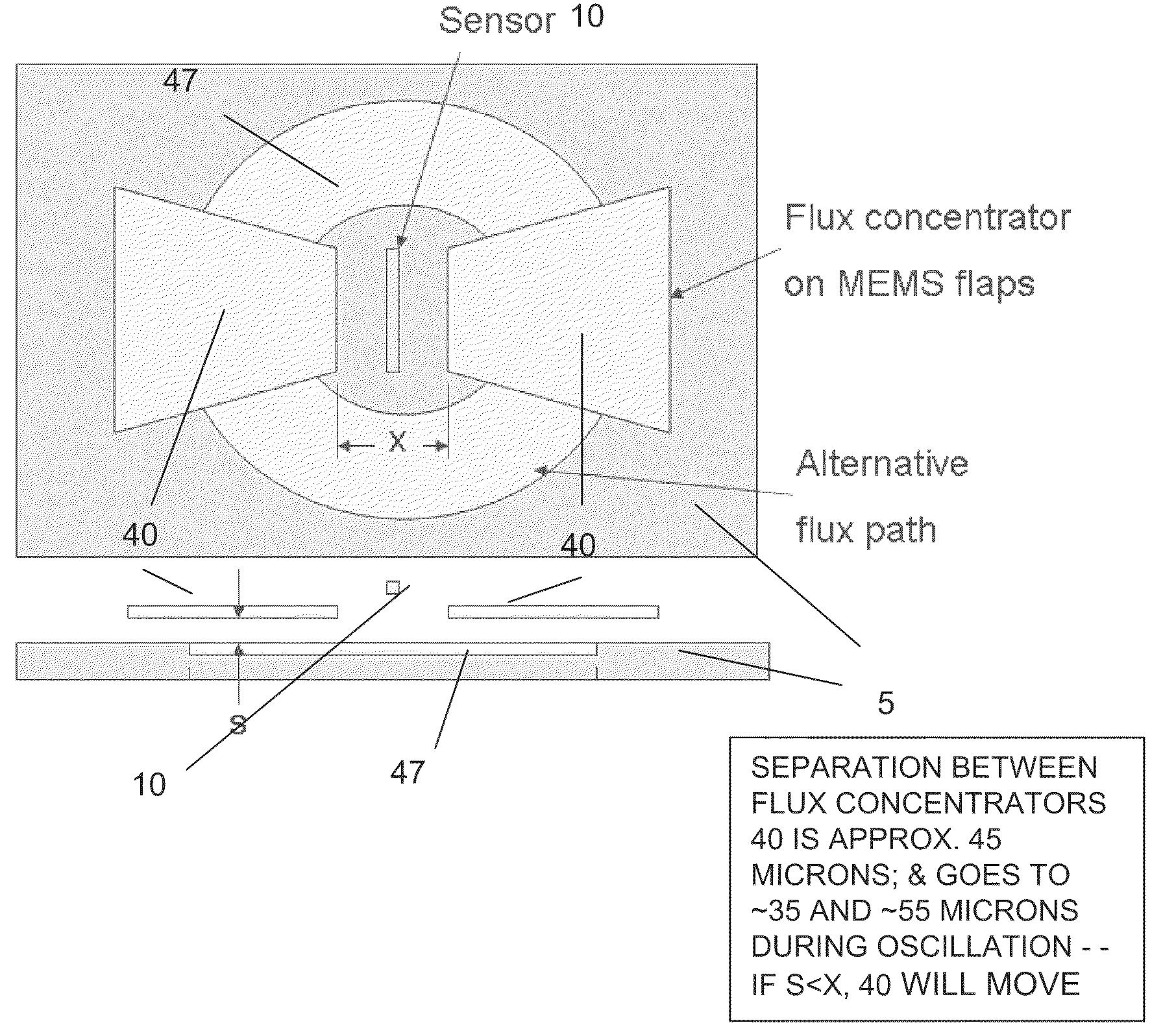
[0059]FIG. 21 illustrates an alternative embodiment of the present invention having a stationary alternate flux path 47.

[0060]FIG. 22 illustrates the design of a wafer having a plurality of MEMs devices mounted thereon.

[0061]FIG. 23 illustrates the de...


PUM


Abstract

A microelectromechanical modulating magnetic sensor comprising a base; a magnetic transducer associated with the base that provides an output in response to a magnetic field; a pair of movable flux concentrators positioned to move relative to the magnetic transducer; the pair of movable flux concentrators having a region of high flux concentration between the pair of movable flux concentrators; the pair of flux concentrators moving together in tandem with the distance between the pair remaining substantially constant during movement; support structure for supporting the pair of movable flux concentrators; a power source for causing the movable flux concentrators to move at a frequency within a predetermined frequency range; whereby when the pair of movable flux concentrators is in a first position the region of high flux concentration is in a first location, and when the pair of movable flux concentrators is in a second position, the region of high flux concentration is in a second position; such that as the flux concentrators move from the first position to the second position the intensity of the flux sensed by the transducer is modulated as the region of high flux concentration approaches and recedes from the location of the transducer.

Description

CROSS REFERENCE TO RELATED APPLICATIONS[0001]This application claims priority to U.S. Provisional Application No. 61 / 088,906 (ARL 08-47) filed Aug. 14, 2008, and U.S. Provisional Application No. 61 / 089,385 (ARL 08-52), filed Aug. 15, 2008, both of which are hereby incorporated by reference as though fully rewritten herein. This application also claims priority to nonprovisional U.S. application Ser. No. 12 / 536,213 (hereby incorporated by reference), entitled “MEMS DEVICE WITH SUPPLEMENTAL FLUX CONCENTRATOR,” filed on Aug. 5, 2009, and nonprovisional U.S. application Ser. No. 12 / 365,398 (hereby incorporated by reference), entitled “MAGNETIC SENSOR METHOD AND APPARATUS,” filed Feb. 9, 2009.STATEMENT OF GOVERNMENT INTEREST[0002]The invention described herein may be manufactured, used, and licensed by or for the United States Government.FIELD OF THE INVENTION[0003]This invention relates broadly to sensors and in particular to the detection of magnetic flux-fields.BACKGROUND OF THE INVEN...

Claims


Application Information

Patent Timeline
Patent Type & Authority Patents(United States)
IPC IPC(8): G01R33/02G01R33/028
CPCG01R33/028G01R33/05
Inventor EDELSTEIN, ALAN S.
Owner ARMY US SEC THE THE
Why Eureka
Try Eureka