Liquid crystal display apparatus for performing alignment process by irradiating light

a liquid crystal display and alignment process technology, applied in non-linear optics, instruments, optics, etc., can solve the problems of uneven display units, unsuitable electrode ends, and display defects, and achieve the effects of reducing the occurrence of display defects due to variations in the direction of initial alignment, high image quality, and improved contrast ratio

Active Publication Date: 2011-03-29
PANASONIC INTELLECTUAL PROPERTY CORP OF AMERICA +1
View PDF28 Cites 6 Cited by
  • Summary
  • Abstract
  • Description
  • Claims
  • Application Information

AI Technical Summary

Benefits of technology

[0022]The object of this invention is to provide a liquid crystal display having a high image quality with an increased contrast ratio by reducing the display defect due to the double radiation of the polarized light on the alignment layer.

Problems solved by technology

In the case where the taper angle of the ends of the electrodes is 90 degrees or more, on the other hand, the tilt angle of the surface of the alignment layer coated on the taper portion of the electrodes partly reaches 90 degrees, and the particular part is not irradiated uniformly with the polarized light for the alignment process, thereby causing an alignment defect.
Also, the taper angle of 90 degrees or more at the ends of the electrodes generates bubbles in the reversely tapered portion in the process of forming the alignment layer and causes the unevenness of the display unit.
Therefore, it is not desirable to form the ends of the electrodes at an angle of 90 degrees or more.

Method used


Image

  • Liquid crystal display apparatus for performing alignment process by irradiating light
  • Liquid crystal display apparatus for performing alignment process by irradiating light
  • Liquid crystal display apparatus for performing alignment process by irradiating light

Examples


first specific example

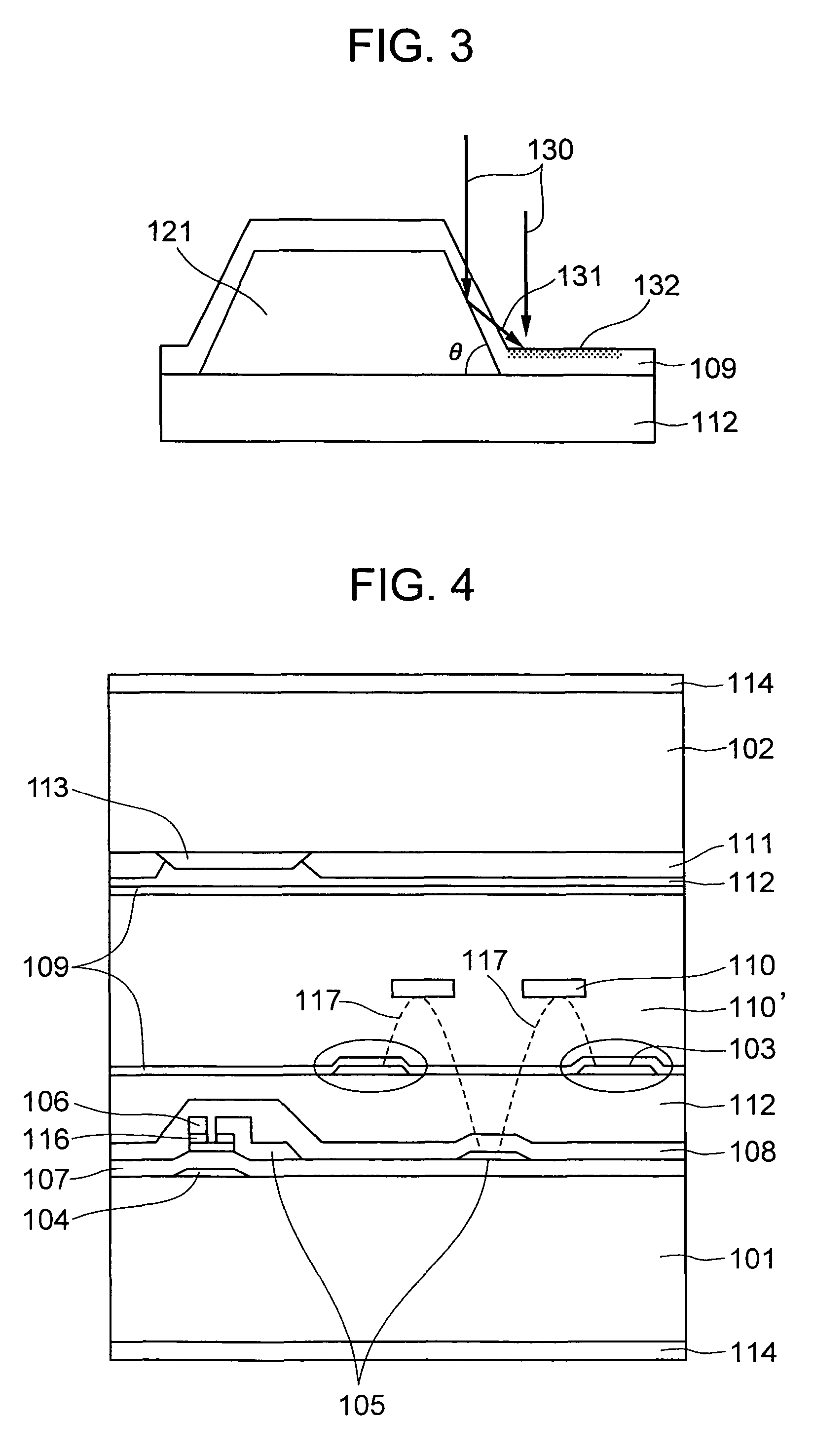
[0090]The first specific example corresponds to the liquid crystal display according to the first embodiment of the invention described above. The first specific example of the invention is explained in detail with reference to FIGS. 4 and 5A, 5B, 5C.

[0091]A liquid crystal display according to the first specific example of the invention is fabricated in the manner described below. Specifically, a glass substrate having a polished surface as thick as 0.7 mm is used as a glass substrate 101 making up an active matrix glass substrate and a glass substrate 102 making up an opposite substrate (color filter substrate). A thin-film transistor 115 formed on the glass substrate 101 includes source electrodes 105, signal electrodes 106, a scanning electrode 104 and a semiconductor film 116. The scanning electrode 104, the common electrode wiring 120, the signal electrodes 106 and the source electrodes 105 are all formed by patterning a chromium film. The interval between a source electrode 10...

second specific example

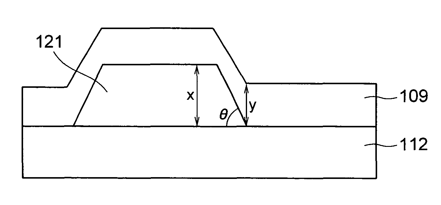
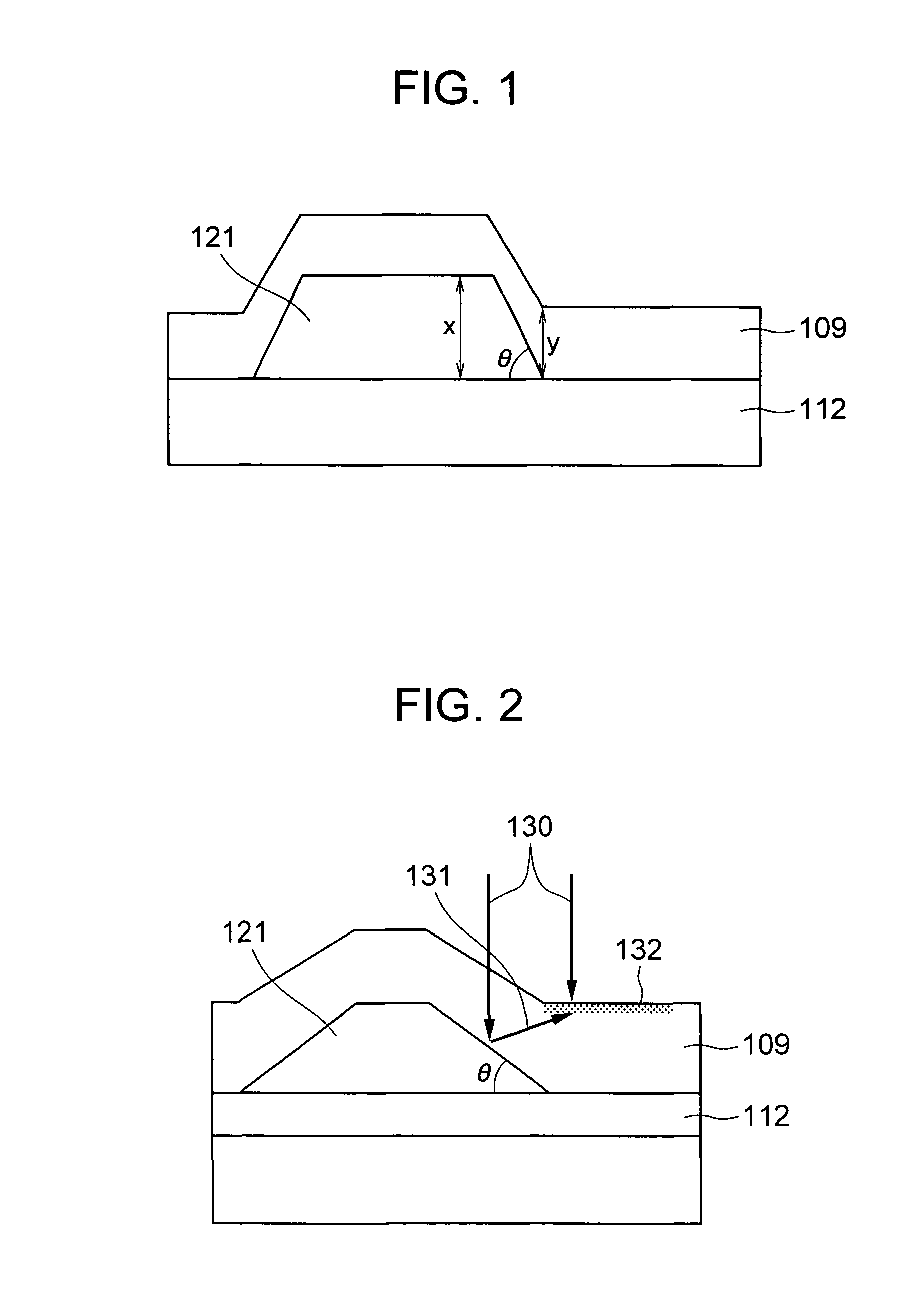
[0102]According to the second specific example, in forming the scanning electrode 104, the common electrode wiring 120, the signal electrode 106 and the source electrodes 105 under the organic insulating film 112, the the taper angle at the ends of these electrodes was set to less than 45 degrees by adjusting the etching conditions. With the other points set similar way to the corresponding points of the first specific example, six IPS-TFT-LCDs were test produced. The thickness of each common electrode 103 is about 50 nm, and that of the alignment layers formed on the two substrates about 80 nm.

[0103]The display quality of these six liquid crystal displays was evaluated, and it was confirmed that these liquid crystal displays are of two categories. In one category, the contrast ratio was 400 or more over the whole surface and the display uniformity was high. In the other category, the contrast ratio is less than 240, light leaks at the electrode edges and the display uniformity is l...

third specific example

[0107]According to the third specific example, like in the first specific example, six IPS-TFT-LCD were test produced. The thickness of the common electrode 103 was about 100 nm, and the thickness of the alignment layers 109 formed on the upper and lower substrates was 85 nm.

[0108]Next, the display quality of the six liquid crystal displays was evaluated, and it was confirmed that these liquid crystal displays are of two categories. In one category, the contrast ratio was 410 or more over the whole surface and the display uniformity was high. In the other category, the contrast ratio is less than 245, light leaks at the electrode edges and the display uniformity is low. With regard to these liquid crystal displays, the observation of the cross section under SEM and the measurement taken of the taper angle at the ends of the common electrode 103 having an alignment layer on the surface thereof showed that the display uniformity is satisfactory for the liquid crystal displays which sa...


PUM

PropertyMeasurementUnit
taper angleaaaaaaaaaa
thicknessaaaaaaaaaa

Abstract

A liquid crystal display includes a pair of substrates including at least one transparent substrate, a liquid crystal layer arranged between the substrates, a plurality of electrodes formed on at least one of the substrates to apply an electric field to the liquid crystal layer, a plurality of active elements connected to the electrodes, an alignment layer formed on the surface of each of the substrates in contact with the liquid crystal layer, and an optical means formed on at least one of the substrates to change the optical characteristics in accordance with the alignment condition of the particles of the liquid crystal layer. The taper angle at the ends of the electrodes is larger than 45 degrees but less than 90 degrees.

Description

BACKGROUND OF THE INVENTION[0001]1. Field of the Invention[0002]The present invention relates to a liquid crystal display, or in particular to an optical alignment layer used for the liquid crystal display.[0003]2. Description of the Related Art[0004]Normally, in the display operation of the liquid crystal display, the electric field is applied to the liquid crystal particles of the liquid crystal layer held between a pair of substrates, thereby changing the direction of alignment of the liquid crystal molecules and the optical characteristics of the liquid crystal layer. The conventional liquid crystal display of what is called active drive type comprising a switching element such as a thin-film transistor for each pixel is represented by the twisted nematic (TN) display system using the rotary polarization of the liquid crystal particles making up the liquid crystal layer, in which a pair of the substrates holding the liquid crystal layer each have an electrode and the electric fi...

Claims


Application Information

Patent Timeline
Patent Type & Authority Patents(United States)
IPC IPC(8): G02F1/1337G02F1/1343G02F1/1335
CPCG02F1/133553G02F1/133753G02F1/134363
Inventor MATSUMORI, MASAKITOMIOKA, YASUSHIMATSUYAMA, SHIGERU
Owner PANASONIC INTELLECTUAL PROPERTY CORP OF AMERICA
Why Eureka
Try Eureka