Tunneling magnetic sensor including platinum layer and method for producing the same

a magnetic sensor and platinum layer technology, applied in the field of magnetic sensors, can solve the problems of reducing operating stability, large variation in sensor resistance, unstable operation, etc., and achieve the effect of reducing the absolute value of vcr, improving operating stability, and high resistance change rate (r/r)

Active Publication Date: 2011-03-29
TDK CORPARATION
View PDF7 Cites 6 Cited by
  • Summary
  • Abstract
  • Description
  • Claims
  • Application Information

AI Technical Summary

Benefits of technology

[0013]Accordingly, the present invention provides a tunneling magnetic sensor including a Ti—O insulating barrier layer and capable of providing a reduced absolute value of VCR, low RA, and a high rate of resistance change (ΔR / R) and a method for producing such a tunneling magnetic sensor.

Problems solved by technology

Higher absolute values of VCR are disadvantageous because they result in larger variations in sensor resistance and decreased operating stability (unstable operation).
High RA causes problems such as difficulty of high-speed data transmission, and a low rate of resistance change (ΔR / R) poses the difficulty of increasing output.

Method used


Image

  • Tunneling magnetic sensor including platinum layer and method for producing the same
  • Tunneling magnetic sensor including platinum layer and method for producing the same
  • Tunneling magnetic sensor including platinum layer and method for producing the same

Examples


examples

Experiment for VCR

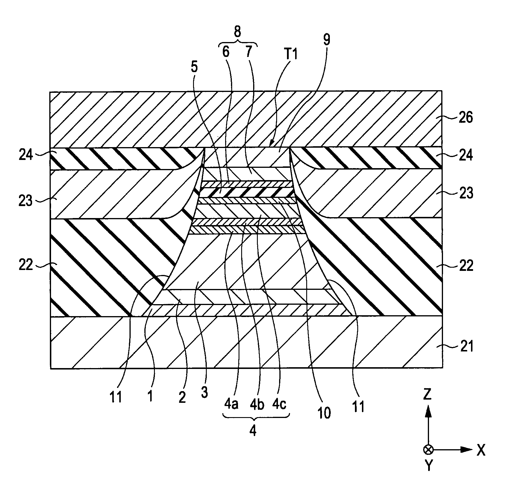
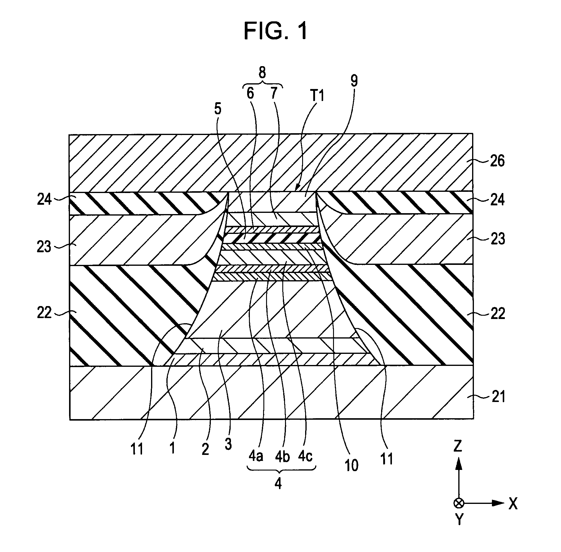
[0096]Tunneling magnetic sensors shown in FIG. 1 were produced. First, a total of six samples were prepared, including Comparative Example 1, Examples 1 to 4, and Reference Example 1.

[0097]The basic film structure of the samples included, from bottom to top, the base layer 1, the seed layer 2, the antiferromagnetic layer 3, the pinned magnetic layer 4, the insulating barrier layer 5, the free magnetic layer 8, and a protective layer. The base layer 1 was formed of tantalum and had an average thickness of about 30 Å. The seed layer 2 was formed of NiFeCr and had an average thickness of about 50 Å. The antiferromagnetic layer 3 was formed of IrMn and had an average thickness of about 70 Å. The first pinned magnetic layer 4a was formed of Co70at %Fe30at % and had an average thickness of about 14 Å. The nonmagnetic intermediate layer 4b was formed of ruthenium and had an average thickness of about 9.1 Å. The second pinned magnetic layer 4c was formed of Co90at % Fe10at...


PUM

PropertyMeasurementUnit
insulatingaaaaaaaaaa
magnetizationaaaaaaaaaa
external magnetic fieldaaaaaaaaaa

Abstract

A tunneling magnetic sensor includes a platinum layer between a pinned magnetic layer and an insulating barrier layer. The platinum layer can probably vary the barrier height (potential height) and barrier width (potential width) of the insulating barrier layer to reduce the absolute value of VCR, thus providing higher operating stability than known tunneling magnetic sensors. In addition, the insulating barrier layer can achieve increased flatness at its bottom interface (where the insulating barrier layer starts to be formed). The tunneling magnetic sensor can therefore provide a higher rate of resistance change (ΔR / R) at low RA than known tunneling magnetic sensors.

Description

CLAIM OF PRIORITY[0001]This application claims benefit of the Japanese Patent Application No. 2006-245410, filed Sep. 11, 2006, which is hereby incorporated by reference.BACKGROUND OF THE INVENTION[0002]1. Field of the Invention[0003]The present invention relates to magnetic sensors utilizing a tunneling effect for use in magnetic sensing apparatuses such as magnetic playback apparatuses, including hard disk drives. In particular, the invention relates to a tunneling magnetic sensor capable of providing a reduced absolute value of VCR (voltage coefficient of resistance), low RA (the product of sensor resistance, R, and sensor area, A), and a high rate of resistance change (ΔR / R) and a method for producing such a tunneling magnetic sensor.[0004]2. Description of the Related Art[0005]A tunneling magnetic sensor (tunneling magnetoresistive element), which utilizes a tunneling effect to cause a resistance change, includes a pinned magnetic layer, a free magnetic layer, and an insulating...

Claims


Application Information

Patent Timeline
Patent Type & Authority Patents(United States)
IPC IPC(8): G11B5/33
CPCB82Y10/00B82Y25/00B82Y40/00G01R33/093G01R33/098H01F10/3295G11B5/3909H01F10/3254H01F41/303H01L43/08G11B5/3906H01F10/3277H10N50/10
Inventor ISHIZONE, MASAHIKOHASEGAWA, NAOYASAITO, MASAMICHIIDE, YOSUKENAKABAYASHI, RYONISHIMURA, KAZUMASA
Owner TDK CORPARATION
Why Eureka
Try Eureka