
System and method for mobile ad hoc network

Active Publication Date: 2011-03-29
AT&T INTPROP I L P
View PDF40 Cites 57 Cited by
  • Summary
  • Abstract
  • Description
  • Claims
  • Application Information

AI Technical Summary

Benefits of technology

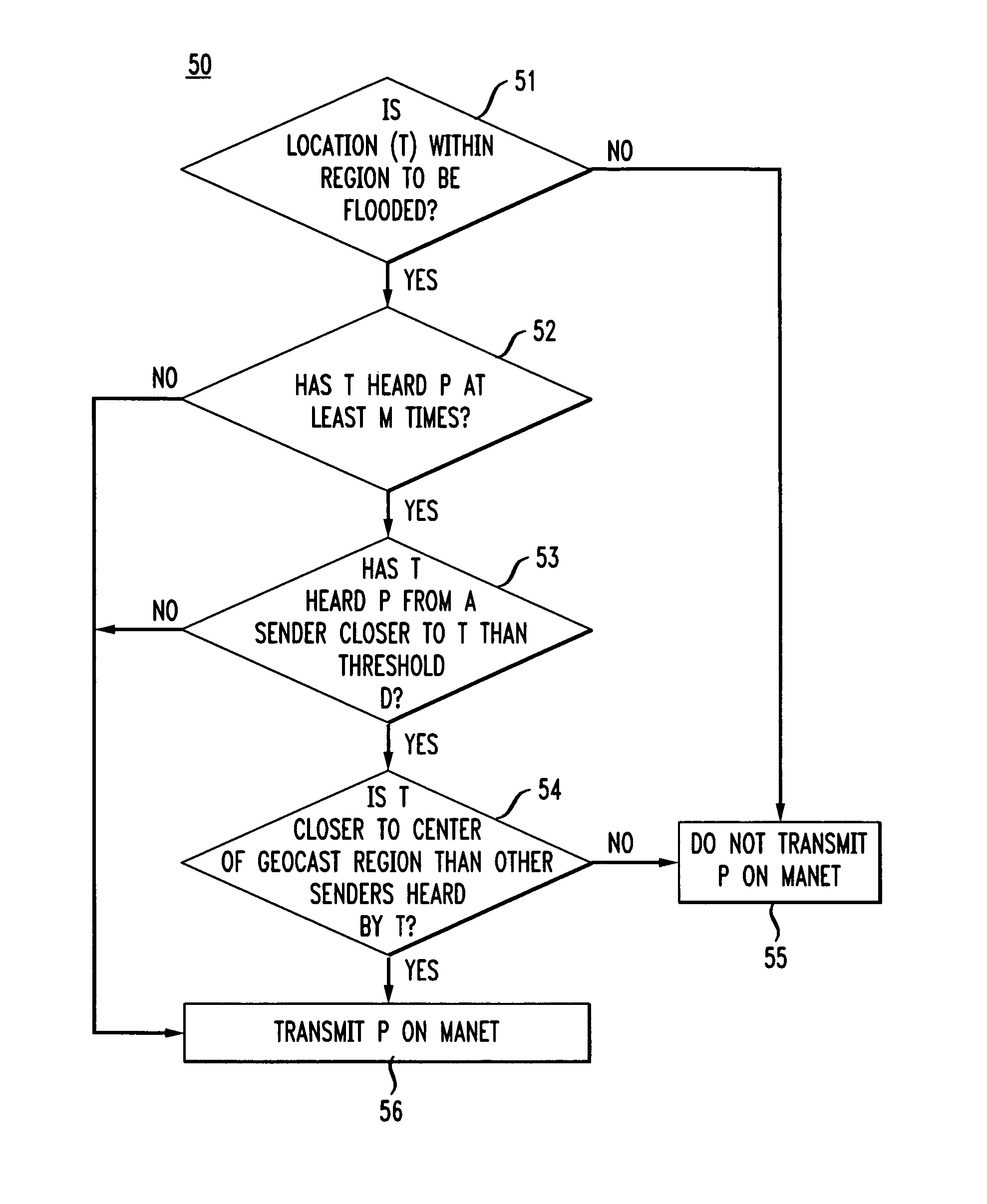
[0011]The present invention provides a more efficient system and method for geocasting data packets in a MANET. This is accomplished by combining the MANET with a long-range network and limiting retransmissions by a wireless terminal based on its proximity to the originating terminal, a retransmitter of the packet, and / or the geocast region. The result is a network in which some retransmissions of geocast packets will be offloaded from the MANET to the long-range network and retransmissions on the MANET will be limited to terminals that are within some minimum distance of the origination wireless terminal and / or the geocast region. In doing this, the number of retransmissions on the MANET and the total number of retransmissions for any given packet will be reduced over the prior art. In addition, use of the long-range network enables packet to be communicated over paths between wireless terminals that are separated by large empty gaps (no intermediate wireless terminals located in the gap) over which communications in the MANET alone would fail, thereby further overcoming limitations of the prior art.
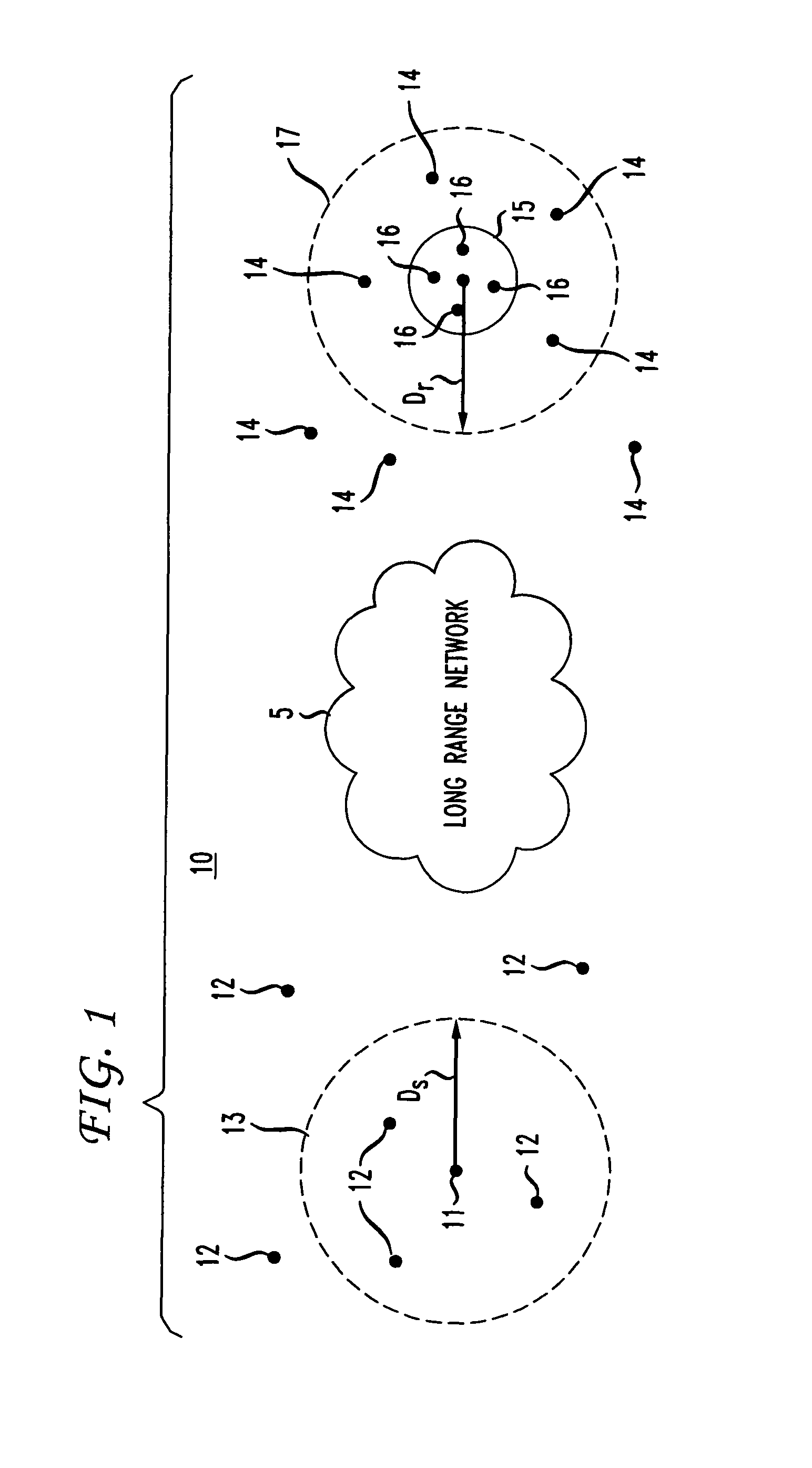
[0013]A geocast in such an embodiment may proceed as follows. A packet is first transmitted from an originating wireless terminal via a location-based flooding algorithm to all wireless terminals within the origination region. Each wireless terminal in the origination region that is long range capable will transmit the packet on the long-range network to long range capable wireless terminals located within the termination region. The wireless terminals located within the termination region will then transmit the packet on the MANET using, for example, a location-based flooding algorithm. Since the geocast region is a subset of the termination region, the location-based flood in the termination region will result in the geocast group receiving the packet, thereby completing the geocast. In this way, for each geocast, not every reachable wireless terminal in the MANET will have to rebroadcast. Instead, only a subset of the wireless terminals located within the origination region and a subset of the wireless terminals located within the termination region will retransmit the packet, thereby reducing the amount of processing power and wireless bandwidth used for each geocast. In addition, by using the long-range network, many-hop paths on the MANET can be replaced by fewer-hop paths taken via long-range network transmissions, thereby reducing packet latency for paths covering long geographic distances.

Problems solved by technology

The intended recipients that are outside the range of the broadcasting terminal, however, will not be able to receive the message.
Although multicasting, and in some cases broadcasting, are effective when the intended recipients are scattered throughout the MANET, they are not efficient for applications where the intended recipients are all located in a defined physical area.
For example, when trying to send messages to everyone in a disaster area or all troops in a given battle venue, multicasting can result in utilizing the processing power of the MANET for many unnecessary transmissions.
That is, multicasting may result in multiple retransmissions or rebroadcasts by wireless terminals that are not the intended recipients and by wireless terminals that are located in areas remote from the disaster area or the battle venue.
Moreover, due to the fact that mobile terminals move often and unpredictably, it is impractical to maintain a (registered) multicast group for each arbitrary geographic region.
Although such present-day location-based flooding algorithms are simple and robust, they are not efficient for geographically large MANETs.
In geographically large MANETs, such algorithms may result in the packets traveling paths having many “hops” and therefore taking a long time to be transmitted from source to destination.
In addition, when the MANET includes a large number of wireless terminals in an extended area, such algorithms tend to result in many unnecessary retransmissions, wasting the resources of the MANET.
Yet further, when the path between the source and the destination terminals are separated by large empty gaps (gaps so large that wireless terminals cannot transmit across the gap), such algorithms fail altogether.

Method used


Image

  • System and method for mobile ad hoc network
  • System and method for mobile ad hoc network
  • System and method for mobile ad hoc network

Examples


Embodiment Construction

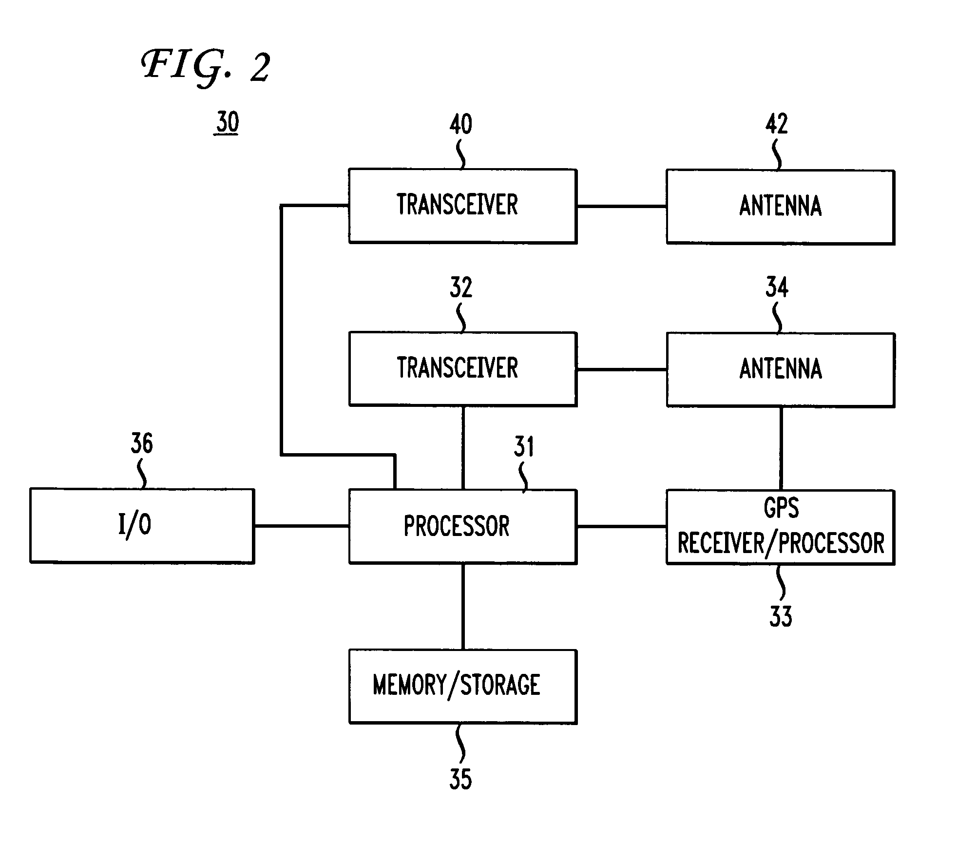
[0019]FIG. 1 shows a network 10 in accordance with an embodiment of the present invention. As shown, network 10 includes a plurality of wireless terminals 11, 12, 14 and 16 that form a MANET. Each wireless terminal 11, 12, 14 and 16 is operable to determine its own geographical location through any type of location determination system including, for example, the Global Positioning System. Each wireless terminal is operable to transmit and receive packets on the MANET. In addition, at any given time, some subset (possibly all) of the wireless terminals may be operable to transmit and receive packets over a long-range network 5. The long-rang network 5 can be any network in which packets can be transmitted from one long-range capable wireless terminal to another long-range capable wireless terminal. Many such packet networks, for example an infrastructure-based network comprising wireless base stations (for up- and down-link) operating on a separate frequency from that used by the MA...


PUM


Abstract

A method and system for geocasting data packets in a MANET. The MANET is combined with a long-range network such that a wireless terminal can decide whether to rebroadcast a geocast packet over the MANET, the long-range network, or not at all, depending on the wireless terminal's proximity to the geocast region, the location of the originating wireless terminal, or both. A wireless terminal close to or within the geocast region can rebroadcast on the MANET, whereas a wireless terminal far from the geocast region can rebroadcast on the long-range network.

Description

RELATED APPLICATION[0001]This application is related to application Ser. No. 11 / 289,899 filed Nov. 30, 2005, now U.S. Pat. No. 7,525,933 B1 entitled “System and Method for Mobile Ad Hoc Network,”.BACKGROUND OF THE INVENTION[0002]The present invention is directed to mobile ad hoc networks (MANETs). More specifically, the present invention is directed to a system and method for multicasting data packets in a MANET.[0003]A MANET is basically a network of mobile wireless terminals, such as wireless phones, that communicate with each other within a given region or area. A MANET does not require or use “base station” terminals to control the communications between the wireless terminals. Each wireless terminal is capable of receiving / transmitting data packets to / from other wireless terminals in the MANET.[0004]In a MANET, when a wireless terminal intends to send the same information to more than one destination (i.e. more than one wireless terminal recipient), it will typically broadcast ...

Claims


Application Information

Patent Timeline
IPC IPC(8): H04W4/00H04W4/02H04W4/029H04W4/50
CPCH04L12/189H04W4/023H04W48/18H04W4/001H04W4/02H04W48/08H04W64/00H04W84/18H04W88/04H04W4/50H04W4/029
Inventor HALL, ROBERT J.
Owner AT&T INTPROP I L P
Learn More