Video input switching and signal processing apparatus

a signal processing and input switching technology, applied in the field of video equipment, can solve the problems of discontinuing carriage, complicated wiring requirements for television viewers,

Inactive Publication Date: 2011-03-29
BARTONFALLS LLC
View PDF48 Cites 17 Cited by
  • Summary
  • Abstract
  • Description
  • Claims
  • Application Information

AI Technical Summary

Benefits of technology

[0006]A system controller, which accepts control signals from a standard infrared-type hand-held remote-controller, handles such tasks as input selection and channel switching, and allows the user to reassign channel designations at will, even including input switching as part of the channel selection. The controller also integrates signals for an optional telephone interface, for pay-per-view billing or other uses. When required, the controller is further capable of enabling descrambling circuitry as appropriate for each signal source. In like manner, specialized modules (as, for example, MPEG decoders and the like) may be enabled or have their operating parameters configured so as to process digitally encoded signals. In a preferred embodiment, the unit may be provided with additional tuner provisions associated with any of the various inputs, for receiving signals in which a primary signal is on one channel, and a secondary signal is on a different channel, as, for example, in the case of a stereoscopic broadcast system in which one channel carried the “left eye” signal, and a second channel carried the “right-eye” signal.

Problems solved by technology

Television viewers are often faced with complicated wiring requirements for integrating the various signal sources into their systems.
This situation was made worse in part by the Federal Cable Regulation Act of 1992, which caused some cable systems to discontinue carriage of local Broadcast stations that insist on receiving a per-subscriber fee to allow retransmission of their signals.
With the availability of signals from direct-broadcast satellites, many consumers will consequently have three different signal sources to choose from when viewing, with the added confusion that all three of these sources may provide channels with the same numerical designation.
A further complication is the integration of cable converters with the public switched telephone network, for billing special event programming and various other pay-per-view schemes.

Method used


Image

  • Video input switching and signal processing apparatus
  • Video input switching and signal processing apparatus
  • Video input switching and signal processing apparatus

Examples


Embodiment Construction

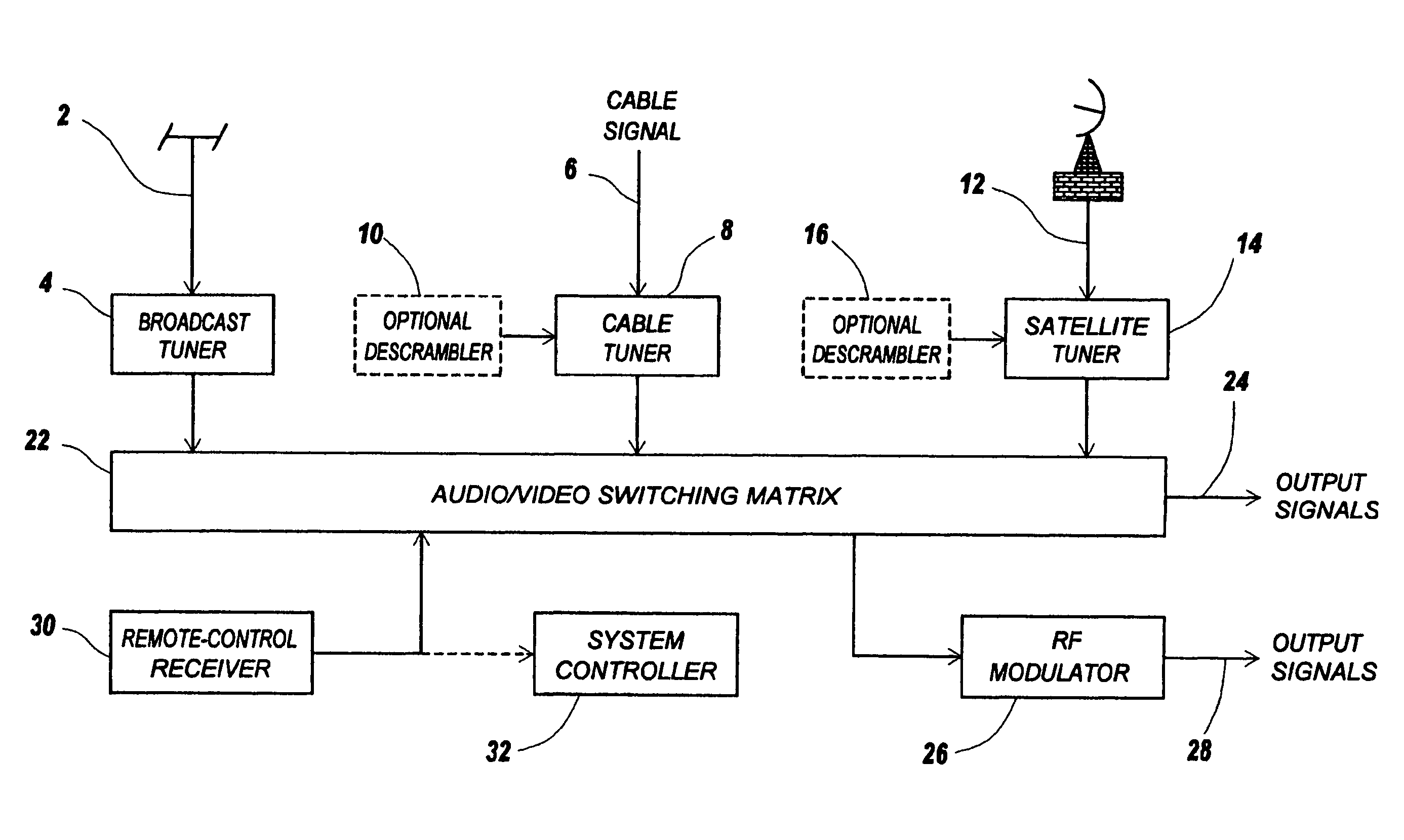
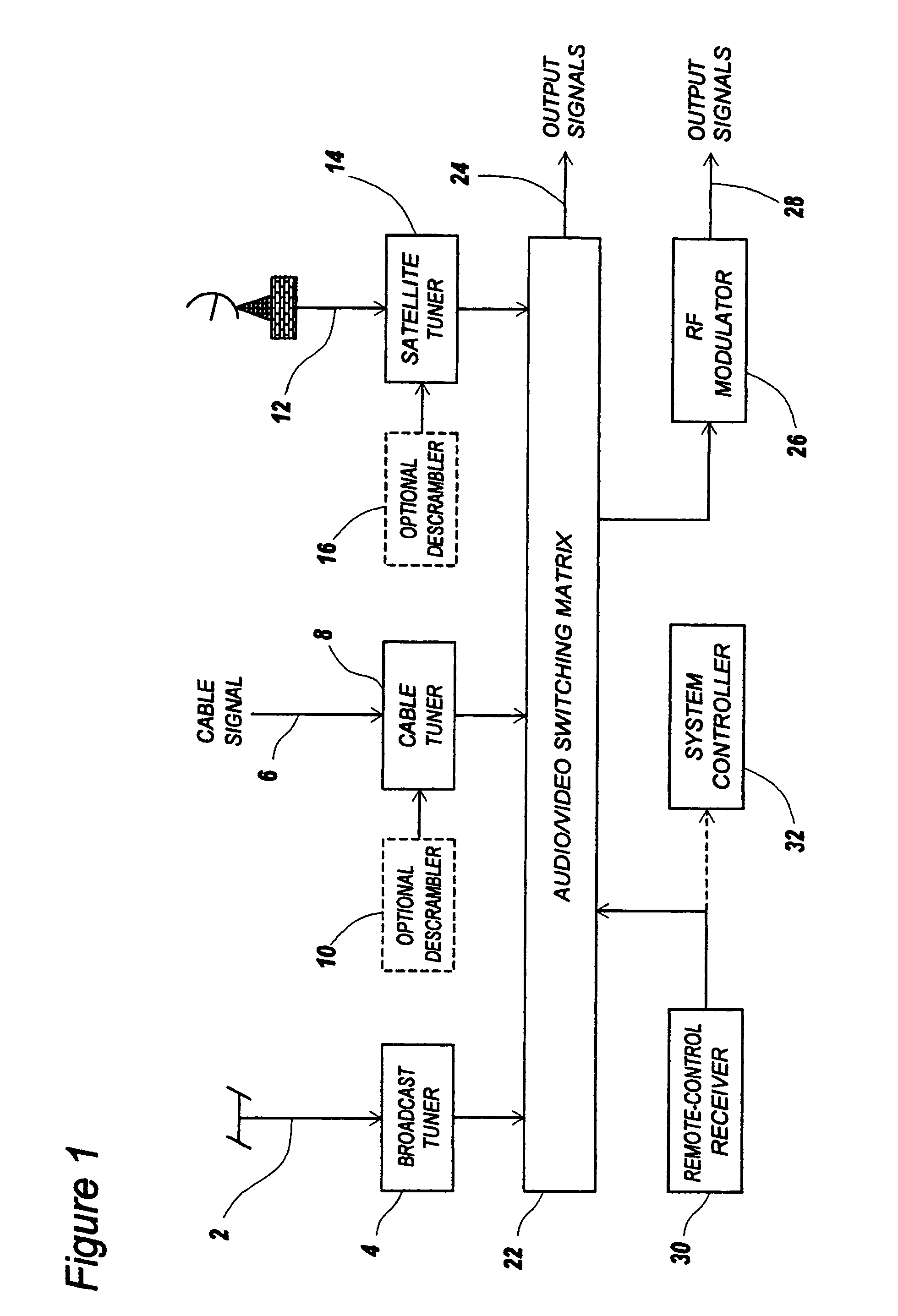
[0009]The invention is explained by way of reference to FIG. 1, which shows the main features of a system having input switching provisions. Broadcast-frequency signals 2 from a standard antenna are received at the broadcast tuner 4. These signals are demodulated into baseband audio and video signals, which then are provided to the audio / video switching matrix 22. Cable system signals 6 are provided to the cable tuner 8, which as an option may include a descrambler module 10; this may be implemented either as an internal circuit board, an internal plug-in module, or an external plug-in unit, and this unit would be compatible with the scrambling system used on the particular cable system. Depending upon the circumstances, one or more of the various tuners may interface to a decoder to receive other specialized information such as teletext or closed-captioning, though not referenced in the figures.

[0010]Optional satellite-receiver signals 12 are provided to the satellite tuner 14, whi...


PUM


Abstract

An apparatus integrates a plurality of television signal sources into a cohesive audio/video environment. Internal provisions include a standard broadcast-frequency tuner, cable tuner as well as other optional inputs such as for a direct-broadcast satellite, previously recorded video material, etc. In the preferred embodiment, means are provided whereby a main or primary program channel may be linked to additional channels providing supplementary information to enhance resolution, sound quality, or to facilitate special effects.

Description

[0001]This application is a continuation of application Ser. No. 08 / 488,691, filed Jun. 8, 1995 now abandoned.FIELD OF THE INVENTION[0002]This invention generally relates to video equipment, and more particularly, to a converter arrangement operative to configure a plurality of input sources into an integrated operating environment.BACKGROUND OF THE INVENTION[0003]Television viewers are often faced with complicated wiring requirements for integrating the various signal sources into their systems. This situation was made worse in part by the Federal Cable Regulation Act of 1992, which caused some cable systems to discontinue carriage of local Broadcast stations that insist on receiving a per-subscriber fee to allow retransmission of their signals. As a result, cable subscribers on these systems must provide their own antennas in order to receive signals from these broadcast stations.[0004]With the availability of signals from direct-broadcast satellites, many consumers will consequen...

Claims


Application Information

Patent Timeline
Patent Type & Authority Patents(United States)
IPC IPC(8): H04N7/173H04N7/10H04N9/00H04N7/16
CPCH04N21/4755H04N21/84H04N21/4113H04N21/4263H04N21/25891H04N21/4532H04N21/4126H04N21/235H04N21/434H04N21/41265
Inventor SCHWAB, BARRY H.POSA, JOHN G.
Owner BARTONFALLS LLC
Why Eureka
Try Eureka