Method for detecting a check-back signal in an optical transmission system

a technology of optical transmission system and check-back signal, which is applied in the direction of transmission monitoring, transmission monitoring/testing/fault-measurement system, electrical apparatus, etc., can solve the problems of reducing the signal noise of the check-back signal, affecting the signal, and affecting the signal disadvantage,

Inactive Publication Date: 2011-04-05
XIEON NETWORKS SARL
View PDF8 Cites 82 Cited by
  • Summary
  • Abstract
  • Description
  • Claims
  • Application Information

AI Technical Summary

Benefits of technology

[0017]A simple signal from a monitoring channel for the network management can be used as a check-back signal. Of great advantage is the high output of the check-back signal in as narrow-band spectral range as possible by concentrating a constant proportion of its output in a defined frequency range. This allows detection, i.e. the recognition of the presence of the check-back signal, even if a regeneration is not possible because of a noise ratio that is too high within the bandwidth of the recognition signal.
[0018]An interesting application of the method is the method for recognizing a line discontinuity, which is executed entirely independently of the effective channels. This means that one or several pump sources can also remain switched off in the transmission system as long as the check-back signal is not detected. As a result, this advantageously excludes any danger to persons from escaping laser light.
[0021]Through the high output of the check-back signal in a narrow-band spectral range and with an amplification that is linear and as far as possible unlimited in amplitude following decoupling, the check-back signal can also be detected even with high noise. The narrow-band filter also eliminates a substantial part of the noise contained in the spectrum.
[0023]One major advantage is the simplicity with which new components can be integrated into a standard transmission system in order to implement the method. The principal requirements for detecting the check-back signal are an encoding module for concentrating the defined proportion of the output of the check-back signal on as narrow-band spectral range as possible and a filter for isolating a spectral line corresponding to the spectral range. Other necessary components, such as, for example, monitoring channel, channel couplers and decouplers, opto-electrical modulator with an amplitude controlled amplifier for the full realization of the method according to the invention are already incorporated in modern transmission systems. This significantly reduces in an advantageous way the cost of realizing the arrangements for implementing the method according to the invention as well as its applications.
[0025]The filter for isolating the narrow-band proportion of the check-back signal generates a narrow band-pass filtering. This then also suppresses the white noise e.g. by increased spontaneous emission. The clock frequency is, for example, selected as narrow-band spectral range for the concentration of a defined proportion of the check-back signal. A CMI coding(Coded Mark Inversion) or a RZ coding (Return to Zero) of the check-back signal, for example, can be used for this. When the ones and zeros are equally distributed, half the entire output of the check-back signal is concentrated in a spectral line at the clock frequency. In order to avoid endless ones or endless zeros in the original check-back signal, there is provision in the encoding module for the data to be scrambled one more time, so that the narrow-band spectral range with half the signal output is secured.

Problems solved by technology

However, the use of methods with a pilot signal still remains costly.
Moreover, the signals can be disadvantageously influenced by experiencing a spectral broadening through modulation.
If the data signal has small signal-to-noise ratios or if the pump source used is switched off, there is a danger that the check-back signal is suppressed in its signal noise by amplitude limiting.

Method used


Image

  • Method for detecting a check-back signal in an optical transmission system
  • Method for detecting a check-back signal in an optical transmission system
  • Method for detecting a check-back signal in an optical transmission system

Examples


Embodiment Construction

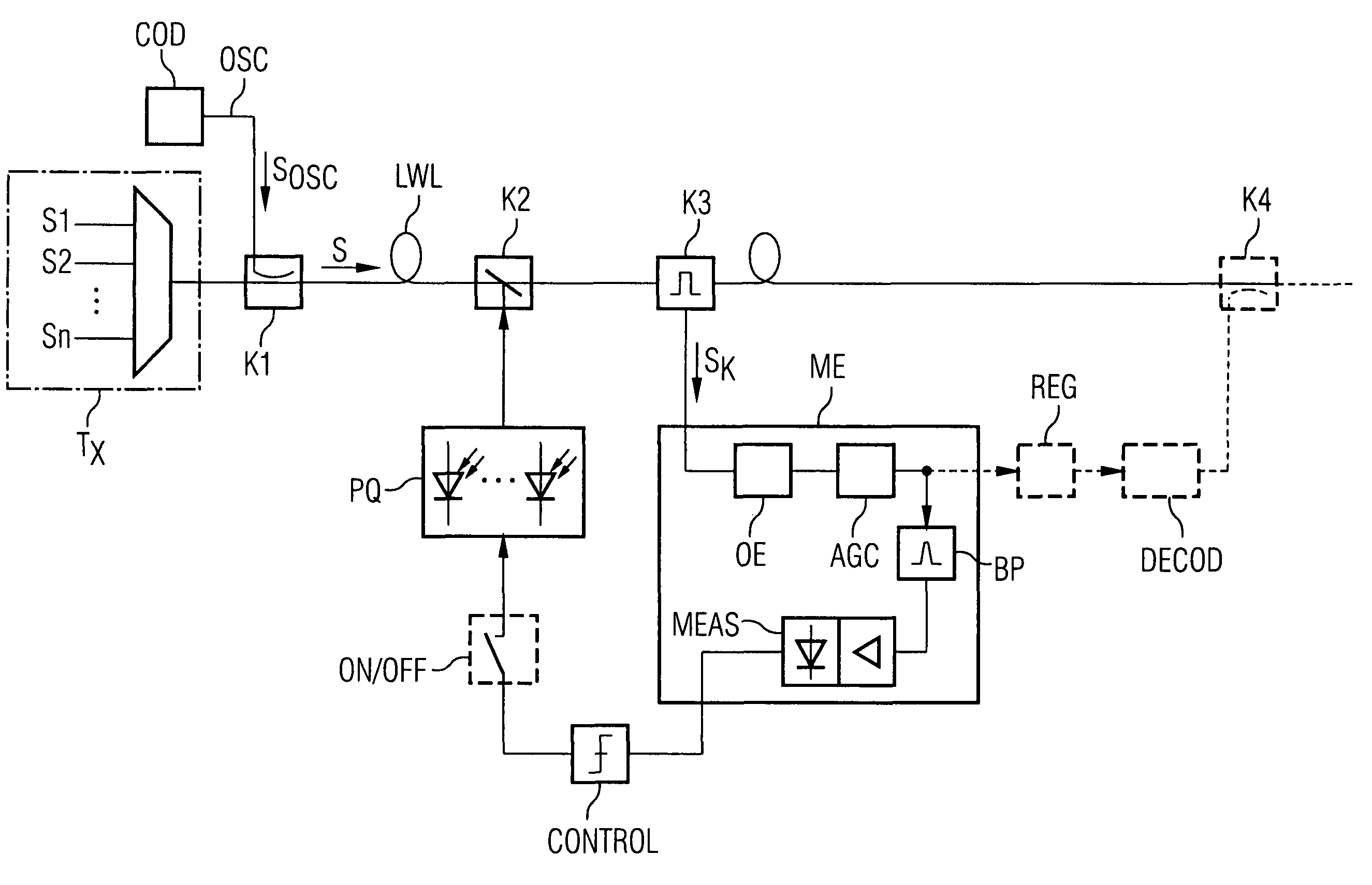
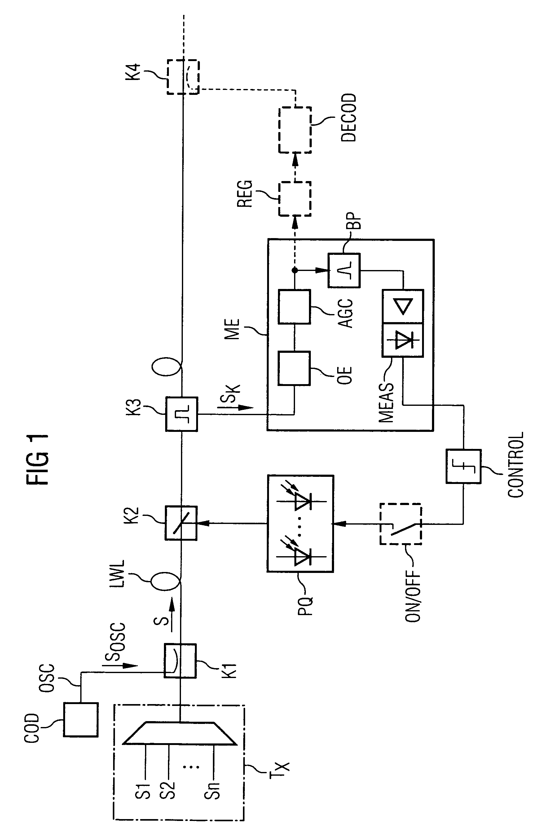
[0030]In FIG. 1 there is an illustration of an arrangement for determining a line discontinuity in accordance with the method according to the invention for detecting a check-back signal. Optical signals S1, S2, . . . , Sn are fed from a transmitting unit Tx into an optical waveguide LWL in a transmission system, said signals are intended, for example, as wavelength or polarization multiplex signals. A first coupler K1 is arranged in the first section of the optical waveguide LWL. An encoding module COD is connected in series to the coupler K1, said encoding module encodes a check-back signal SOSC from a monitoring channel OSC of the transmission system in such a way that defined proportion of its output is concentrated in a narrow-band spectral range. To this end, the encoding module has a scrambler with subsequent CMI or RZ encoding. Here the clock frequency of the check-back signal is selected as the centre of the spectral range. In a further section, there are placed a second co...


PUM


Abstract

The invention relates to a method for detecting a check-back signal in a transmission system for optical signals. According to said method, a constant proportion of the output in a defined frequency range of the check-back signal is concentrated in a narrow-band spectral range and is determined after a transmission phase by means of a narrow-band detection of the concentrated energy around the spectral range. If no signal is identified during the narrow-band detection, a line interruption is determined and no pump source is switched on for safety reasons. The narrow-band detection of the check-back signal also allows the transmission attenuation of the transmission system to be measured.

Description

CROSS REFERENCE TO RELATED APPLICATIONS[0001]This application is the US National Stage of International Application No. PCT / DE03 / 01075, filed Apr. 1, 2003 and claims the benefit thereof. The International Application claims the benefits of German application No. 10216279.4 filed Apr. 12, 2002, both of the applications are incorporated by reference herein in their entirety.FIELD OF INVENTION[0002]The invention relates to a method, device, and arrangement for detecting a check-back signal in an optical transmission system.BACKGROUND OF INVENTION[0003]In many cases, line discontinuities must be recognized in optical transmission systems and lasers and / or optical amplifications switched off, so as to avoid any danger to persons. Under the term, “automatic laser shutdown (ALS)”, such measures form part of international standards.[0004]DE 10046104.2 discloses a method and a device for recognizing line discontinuities in an optical WDM system with at least one optical amplifier on an optic...

Claims


Application Information

Patent Timeline
Patent Type & Authority Patents(United States)
IPC IPC(8): H04B10/08H04B10/00H04B10/02H04B10/077
CPCH04B10/0771H04B10/0775H04B2210/08
Inventor GENTNER, GUIDONEUMANN, RENETHANHAUSER, GERHARD
Owner XIEON NETWORKS SARL
Why Eureka
Try Eureka