Heat dissipation structure for communication chassis

a technology of communication chassis and heat dissipation structure, which is applied in the direction of insulated conductors, cables, instruments, etc., can solve the problems of significant impact on reliability and life low thermal conductivity of communication chassis materials, and high heat generation of electronic communication equipment, so as to improve heat dissipation structure, and quickly dissipate heat

Inactive Publication Date: 2011-04-12
ASIA VITAL COMPONENTS SHENZHEN CO LTD
View PDF17 Cites 14 Cited by
  • Summary
  • Abstract
  • Description
  • Claims
  • Application Information

AI Technical Summary

Benefits of technology

[0012]A primary object of the present invention is to provide an improved heat dissipation structure for communication chassis, which includes at least one first copper heat absorption component and at least one first heat pipe assembly. The first heat pipe assembly serves to transfer heat absorbed by the first copper heat absorption component to a section not in contact with the first copper heat absorption component to quickly dissipate the heat.
[0013]A further object of the present invention is to provide the above improved heat dissipation structure for communication chassis, which has excellent heat dissipation effect.
[0014]A still further object of the present invention is to provide the above improved heat dissipation structure for communication chassis, which prolongs the lifetime of the equipments arranged in the communication chassis.
[0015]A still further object of the present invention is to provide the above improved heat dissipation structure for communication chassis, which ensures stable quality of communication signals.
[0016]A still further object of the present invention is to provide the above improved heat dissipation structure for communication chassis, which provides increased heat dissipation area for more uniformly and quickly dissipating the heat.
[0017]According to the above objects, the heat dissipation structure for communication chassis of the present invention includes an enclosure having at least one first copper heat absorption component and at least one first heat pipe assembly. The first copper heat absorption component and the first heat pipe assembly are disposed in the enclosure. The first heat pipe assembly is connected with the first copper heat absorption component and a section not in contact with the first copper heat absorption component. The first heat pipe assembly includes multiple first heat pipes each having at least one first heat absorption end and at least one first heat dissipation end. The first heat absorption end transfers the heat absorbed by the first copper heat absorption component to the first heat dissipation end. The first heat dissipation end then transfers the heat to the section not in contact with the first copper heat absorption component to dissipate the heat. Accordingly, the heat can be quickly and uniformly distributively transferred to the enclosure for dissipating the heat at high efficiency.

Problems solved by technology

When operating, the electronic communication equipments generate high heat.
Owing to the limitation of the current casting technique, the material of the communication chassis has low thermal conductivity.
In the case that the temperature rises to a value beyond a tolerable range, the reliability and lifetime of the electronic communication equipments will be significantly affected.
However, such solution results in another problem of heavy weight of the communication chassis.
As a result, in operation, the temperature in the communication chassis often rises quickly to result in poor quality of communication signals or even crash of the heat-generating components 131.
According to the aforesaid, the conventional communication chassis has the following defects:1. The conventional communication chassis has poor heat dissipation effect.2. The communication equipments arranged in the conventional communication chassis are likely to crash.3. The temperature in the conventional communication chassis often rises to result in poor quality of communication signals.4. The lifetime of the communication equipments arranged in the conventional communication chassis is shortened.5. The damage ratio of the communication equipments arranged in the conventional communication chassis is higher.

Method used


Image

  • Heat dissipation structure for communication chassis
  • Heat dissipation structure for communication chassis
  • Heat dissipation structure for communication chassis

Examples


Embodiment Construction

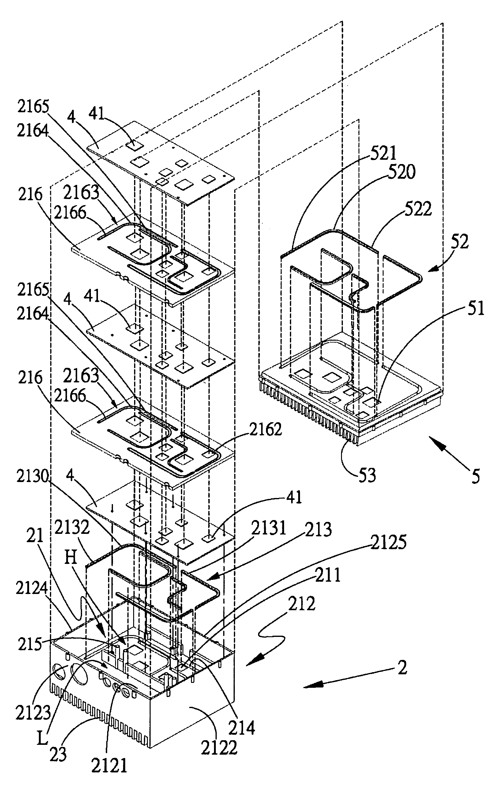
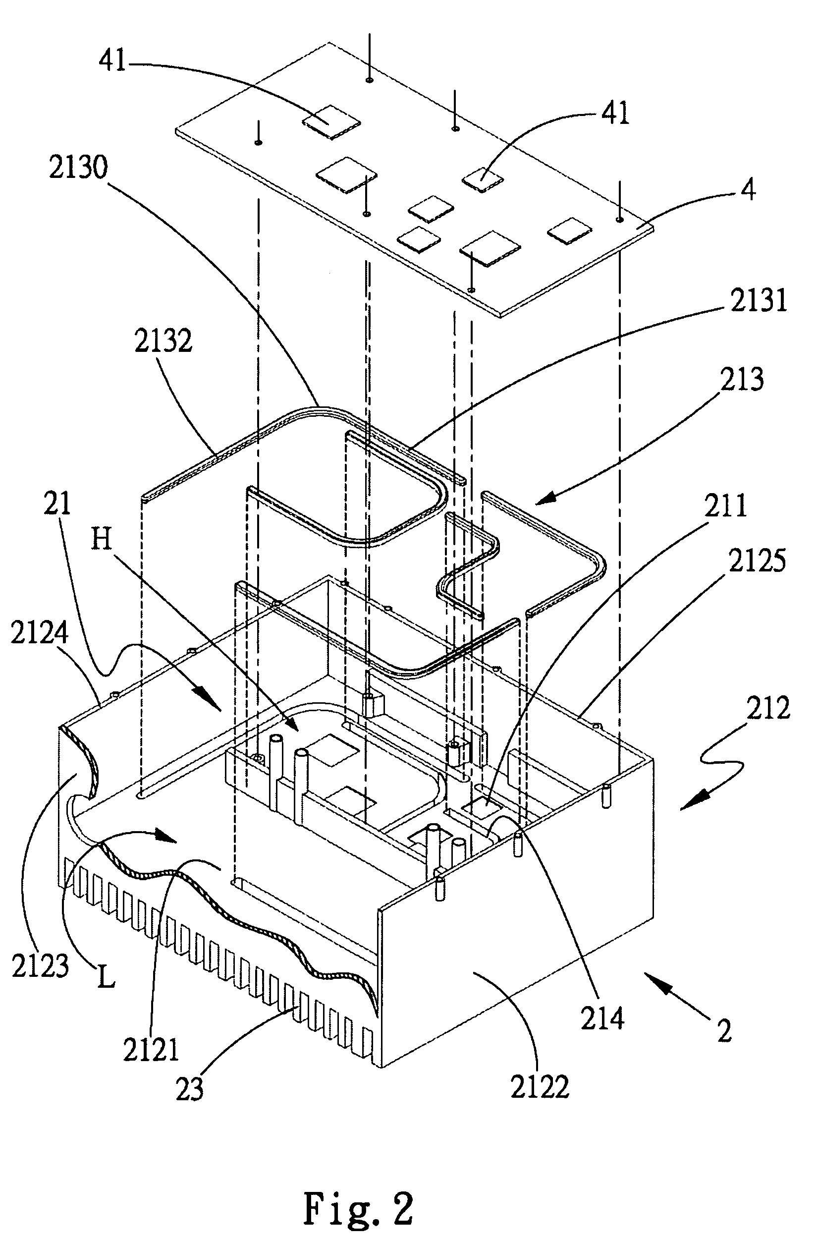
[0025]Please refer to FIG. 2. According to a preferred embodiment, the heat dissipation structure for communication chassis of the present invention includes an enclosure 2 defining a receiving space 21 and having multiple radiating fins 23 disposed on an outer face of the enclosure 2 opposite to the receiving space 21. The enclosure 2 includes at least one first copper heat absorption component 211 and at least one first heat pipe assembly 213. The first heat pipe assembly 213 is disposed in the receiving space 21 of the enclosure 2 and connected with the first copper heat absorption component 211 and a section 212 not in contact with the first copper heat absorption component 211. The first heat pipe assembly 213 serves to transfer heat absorbed by the first copper heat absorption component 211 to the section 212 to dissipate the heat. The section 212 not in contact with the first copper heat absorption component 211 is an area distal from the first copper heat absorption componen...


PUM


Abstract

A heat dissipation structure for communication chassis. The heat dissipation structure includes an enclosure. At least one first copper heat absorption component and at least one first heat pipe assembly are disposed in the enclosure. The first heat pipe assembly is connected with the first copper heat absorption component and a section not in contact with the first copper heat absorption component. The first heat pipe assembly serves to quickly transfer heat absorbed by the first copper heat absorption component to the section not in contact with the first copper heat absorption component to dissipate the heat.

Description

FIELD OF THE INVENTION[0001]The present invention relates generally to a heat dissipation structure for communication chassis, and more particularly to an improved heat dissipation structure for communication chassis, which includes at least one first copper heat absorption component and at least one first heat pipe assembly. The first heat pipe assembly serves to transfer heat absorbed by the first copper heat absorption component to a section not in contact with the first copper heat absorption component so as to quickly dissipate the heat.BACKGROUND OF THE INVENTION[0002]It is known that the conventional electronic communication equipments are enclosed in a communication chassis. When operating, the electronic communication equipments generate high heat. The communication chassis is a closed cabinet, which is generally made of metal material by once casting. Owing to the limitation of the current casting technique, the material of the communication chassis has low thermal conduct...

Claims


Application Information

Patent Timeline
Patent Type & Authority Patents(United States)
IPC IPC(8): H05K7/20G06F1/20
CPCH05K7/20336
Inventor HUANG, CHIU-MAOHUANG, CHANG-MOU
Owner ASIA VITAL COMPONENTS SHENZHEN CO LTD
Why Eureka
Try Eureka