
Linear electron source, evaporator using linear electron source, and applications of electron sources

a linear electron source and electron source technology, applied in the field of linear electron source, evaporator using linear electron source, and applications of electron source, can solve problems such as the tendency to reduce manufacturing costs

Active Publication Date: 2011-04-19
APPLIED MATERIALS INC
View PDF11 Cites 7 Cited by
  • Summary
  • Abstract
  • Description
  • Claims
  • Application Information

AI Technical Summary

Benefits of technology

The solution enables efficient charging and processing of thick webs or foils by ensuring uniform electron beam distribution and high energy implantation, enhancing manufacturing throughput and quality.

Problems solved by technology

Modern manufacturing processes for capacitors on large area substrates or webs, for manufacturing of large area foils, for manufacturing of thin-film solar cells, and the like have a tendency towards decreasing manufacturing costs by enlarging the substrates or webs.

Method used


Image

  • Linear electron source, evaporator using linear electron source, and applications of electron sources
  • Linear electron source, evaporator using linear electron source, and applications of electron sources
  • Linear electron source, evaporator using linear electron source, and applications of electron sources

Examples


Embodiment Construction

[0031]Reference will now be made in detail to the various embodiments of the invention, one or more examples of which are illustrated in the figures. Within the following description of the drawings, the same reference numbers refer to same components. Generally, only the differences with respect to individual embodiments are described. Each example is provided by way of explanation of the invention and is not meant as a limitation of the invention. For example, features illustrated or described as part of one embodiment can be used on or in conjunction with other embodiments to yield yet a further embodiment. It is intended that the present invention includes such modifications and variations.

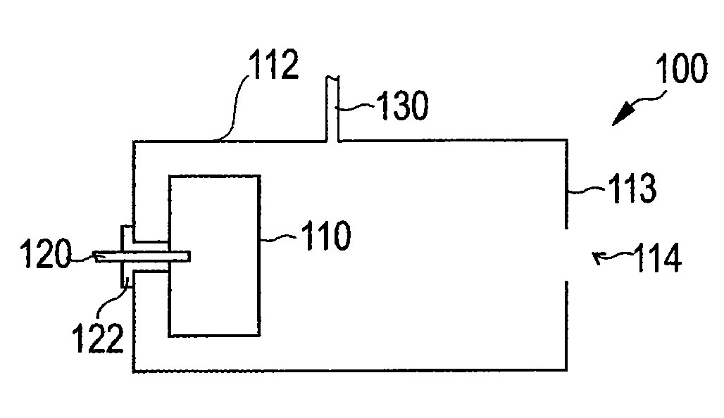
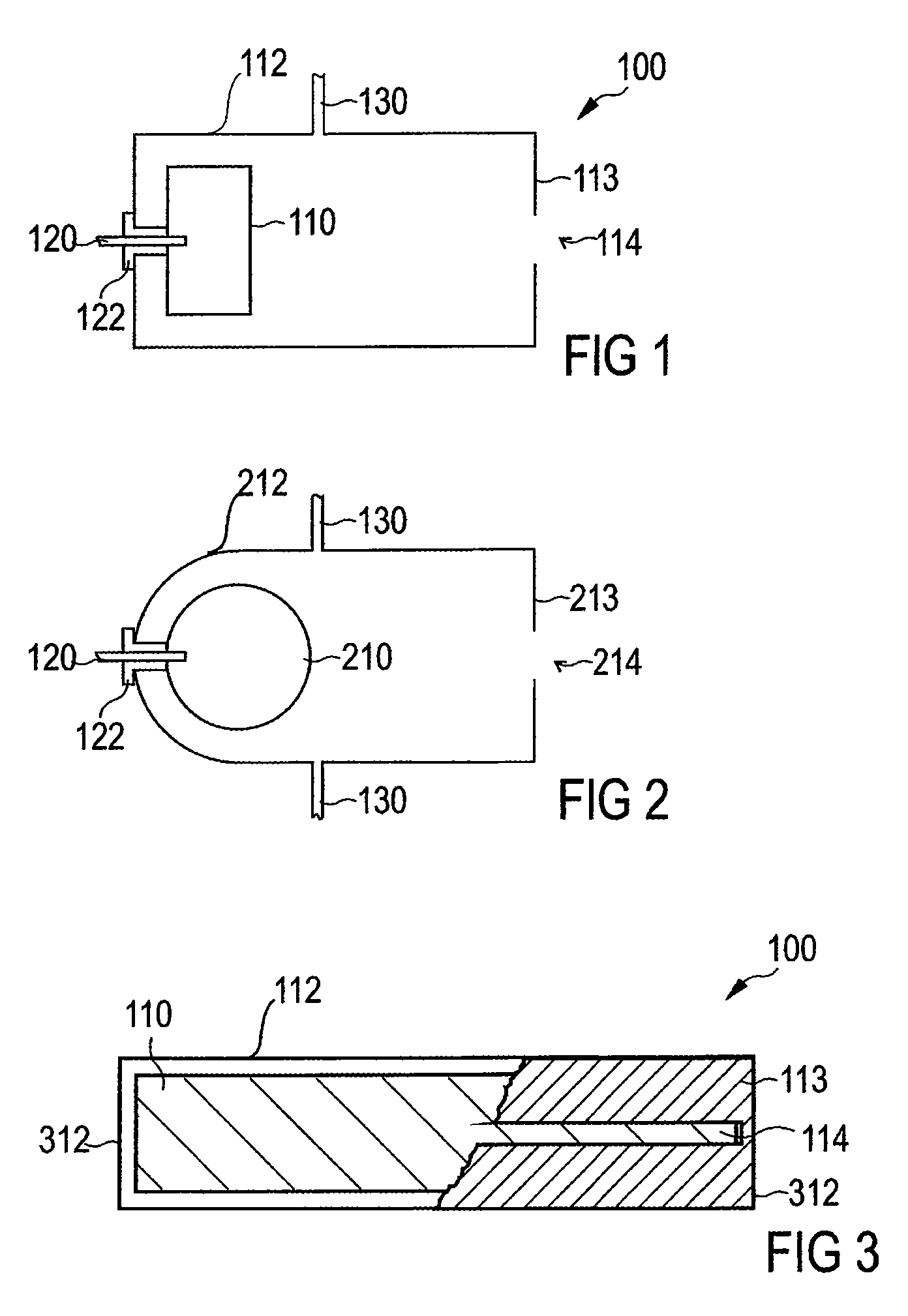
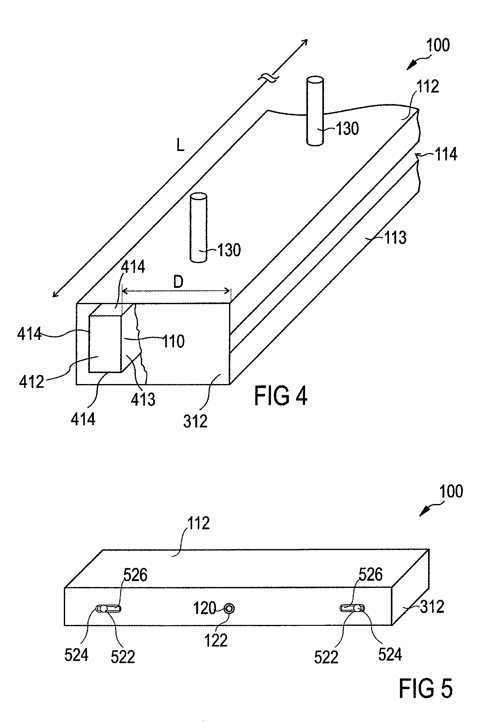
[0032]Embodiments of the present invention relate to linear electron sources and method of operating linear electron sources, which can be used for a plurality of applications. Thereby, the length and / or the height of the cathode is increased for improving modem manufacturing methods of films,...


PUM

PropertyMeasurementUnit
thicknessaaaaaaaaaa
thicknessaaaaaaaaaa
voltageaaaaaaaaaa

Abstract

A method of charging a web or foil is described. The method includes guiding a web or foil having a thickness of 10 μm or larger with at least on roller; providing a linear electron source having a housing acting as an anode, the housing having side walls; a slit opening in the housing for trespassing of a linear electron beam, the slit opening defining a length direction of the source; a cathode being arranged within the housing and having a first side facing the slit opening; at least one gas supply for providing a gas into the housing; and a power supply for providing a high voltage between the anode and the cathode; and emitting the linear electron beam, wherein the high voltage is adjusted for providing an electron energy to implant electrons of the electron beam within the web or foil.

Description

FIELD OF THE INVENTION[0001]The invention relates to an electron source and a method of operating an electron source. In particular, it relates to a linear electron source for producing a linear electron beam with a plurality of electron energies with a distribution of energies. Further, it relates to applications for electron sources and systems making use of an electron source.BACKGROUND OF THE INVENTION[0002]Electron sources are known from a plurality of fields. Thereby, for example, electron beams are used for material modification, charging of surfaces, imaging of samples, and the like.[0003]Modern manufacturing processes for capacitors on large area substrates or webs, for manufacturing of large area foils, for manufacturing of thin-film solar cells, and the like have a tendency towards decreasing manufacturing costs by enlarging the substrates or webs. Further, substrate sizes are increased to speed up manufacturing processes. In order to increase the throughput of a manufact...

Claims


Application Information

Patent Timeline
Patent Type & Authority Patents(United States)
IPC IPC(8): H01J49/08H01J37/305
CPCC23C14/22C23C14/243H01J37/3053H01J37/077C23C14/30
Inventor KLEMM, GUENTERHACKER, VOLKERLOTZ, HANS-GEORG
Owner APPLIED MATERIALS INC
Learn More