Variable lens

a variable lens and lens technology, applied in the field of variable lenses, can solve the problems of unsatisfactory optical effect in such an arrangement, insufficient knowledge of known devices, and negative influence on the quality of monochromatic image, so as to reduce acceleration and positional influence

Inactive Publication Date: 2011-04-19
CARL ZEISS MEDITEC AG
View PDF19 Cites 15 Cited by
  • Summary
  • Abstract
  • Description
  • Claims
  • Application Information

AI Technical Summary

Benefits of technology

[0017]In order, for instance, to reduce acceleration and positional influences, liquids with a similar or identical density can be provided as the fluids.

Problems solved by technology

It is known from imaging optics that monochromatic image quality is negatively affected by higher order aberrations.
It has been determined that such known devices are inadequate in two respects: first, they only permit the dioptric refractive power to be influenced, which is not adequate for many applications; second, the quality of the optical effect in such an arrangement is not adequate for many requirements.

Method used


Image

  • Variable lens
  • Variable lens
  • Variable lens

Examples


Embodiment Construction

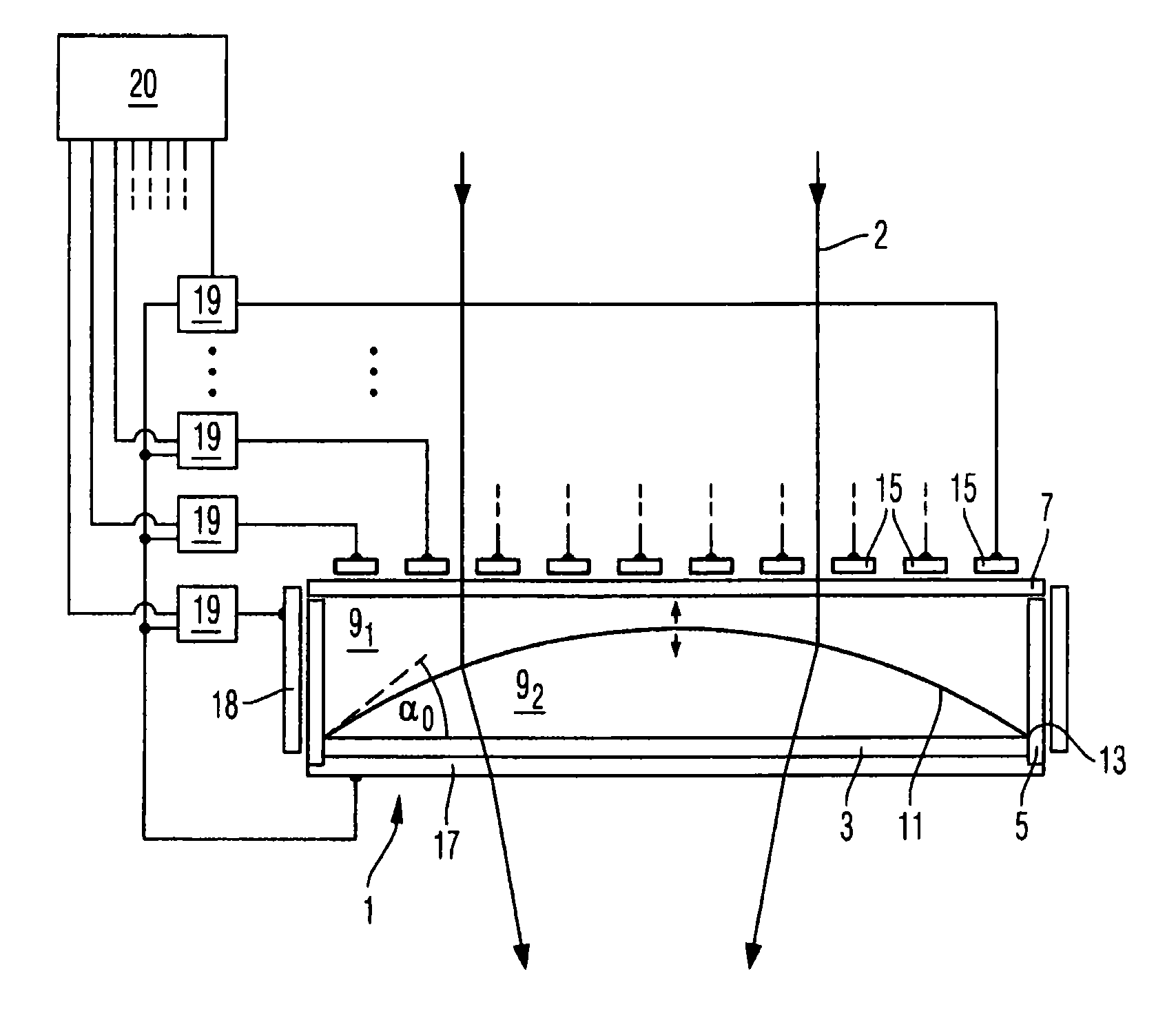
[0041]FIG. 1 depicts a variable lens in which a chamber 1 has a base area 3, an edge area 5, and a cover area 7. The chamber 1 contains two dielectric fluids 91 and 92 with densities d1 and d2, dielectric constants ∈1 and ∈2, and refractive indices n1 and n2, respectively. Due to their limited miscibility, the two fluids form

[0042]a (phase) boundary surface 11 between them. Both fluids can be slightly soluble in a different fluid. The boundary surface 11 is limited by a circumferential area 13 that is part of the chamber 1. In addition, the two fluids 91 and 92 have adhesions to the surface material of the circumferential area 13 and cohesions, from which a contact angle α0 results between the surface of the circumferential area 13 and the boundary surface 11.

[0043]Furthermore the chamber 1 has electrodes 15, 17 that in this example are arranged on the cover area 7 and the base area 3. In this example the chamber 1 is cylindrical, the electrode 15 comprises a plurality of concentric...


PUM


Abstract

The invention relates to a variable lens for controlling electromagnetic radiation that interacts with said lens in a controlled manner. The lens includes a container; a first dielectric fluid that is held in the container; a second dielectric fluid that is held in the container, a phase boundary layer between the first and the second fluid. The relative dielectric constant of the first fluid is different from a relative dielectric constant of the second fluid. At least one first electrode; and at least one second electrode is positioned in relation to the first electrode in such a way that an electric current that is applied between the first and the second electrode generates an electric field, which infiltrates the phase boundary layer.

Description

Related Applications[0001]This application claims priority to PCT Application No. PCT / EP2006 / 001039, filed Feb. 7, 2006 and German Application No. 10 2005 005 933.3, filed Feb. 9, 2005, the disclosures of which are hereby incorporated by reference in their entirety.Field of the Invention[0002]The present invention relates to a variable lens, and in particular to a lens, the interactive properties of which can be influenced with electromagnetic radiation (for instance light including IR and / or UV light). The invention particularly relates to a variable lens for controllably influencing the radiation that interacts with the lens.BACKGROUND OF THE INVENTION[0003]It is known from imaging optics that monochromatic image quality is negatively affected by higher order aberrations. Production of aspherical lenses or reflecting lenses for eliminating or suppressing these aberrations has become known. It is also possible to compensate fixed aberrations with monolithic phase plates in order to...

Claims


Application Information

Patent Timeline
Patent Type & Authority Patents(United States)
IPC IPC(8): G02B1/06
CPCG01J3/02G01J3/0205G01J3/12G02B3/0012G02B3/0075G02B27/0025G02B5/005G02B26/00G02B26/005G02B26/0883G02B3/14
Inventor MOHR, THOMASDICK, MANFREDKUEHNERT, JUERGEN
Owner CARL ZEISS MEDITEC AG
Why Eureka
Try Eureka