Optical head carrying device, integrated circuit for optical head carrying device, focusing lens driving device and integrated circuit for focusing lens driving device

A technology of transfer device and condensing lens, applied in optical recording head, beam guiding device, recording/reproducing by optical method, etc., can solve problems such as increase of device startup time and decrease of data readout speed, etc.

Inactive Publication Date: 2009-06-10
PANASONIC CORP
View PDF2 Cites 4 Cited by
  • Summary
  • Abstract
  • Description
  • Claims
  • Application Information

AI Technical Summary

Problems solved by technology

[0011] If the focus control system becomes abnormal, the optical head transfer device needs to be restarted, etc., resulting in an increase in the start-up time of the device, a decrease in the data read speed from the optical disc, etc.

Method used


Image

  • Optical head carrying device, integrated circuit for optical head carrying device, focusing lens driving device and integrated circuit for focusing lens driving device
  • Optical head carrying device, integrated circuit for optical head carrying device, focusing lens driving device and integrated circuit for focusing lens driving device
  • Optical head carrying device, integrated circuit for optical head carrying device, focusing lens driving device and integrated circuit for focusing lens driving device

Examples


Embodiment approach 1

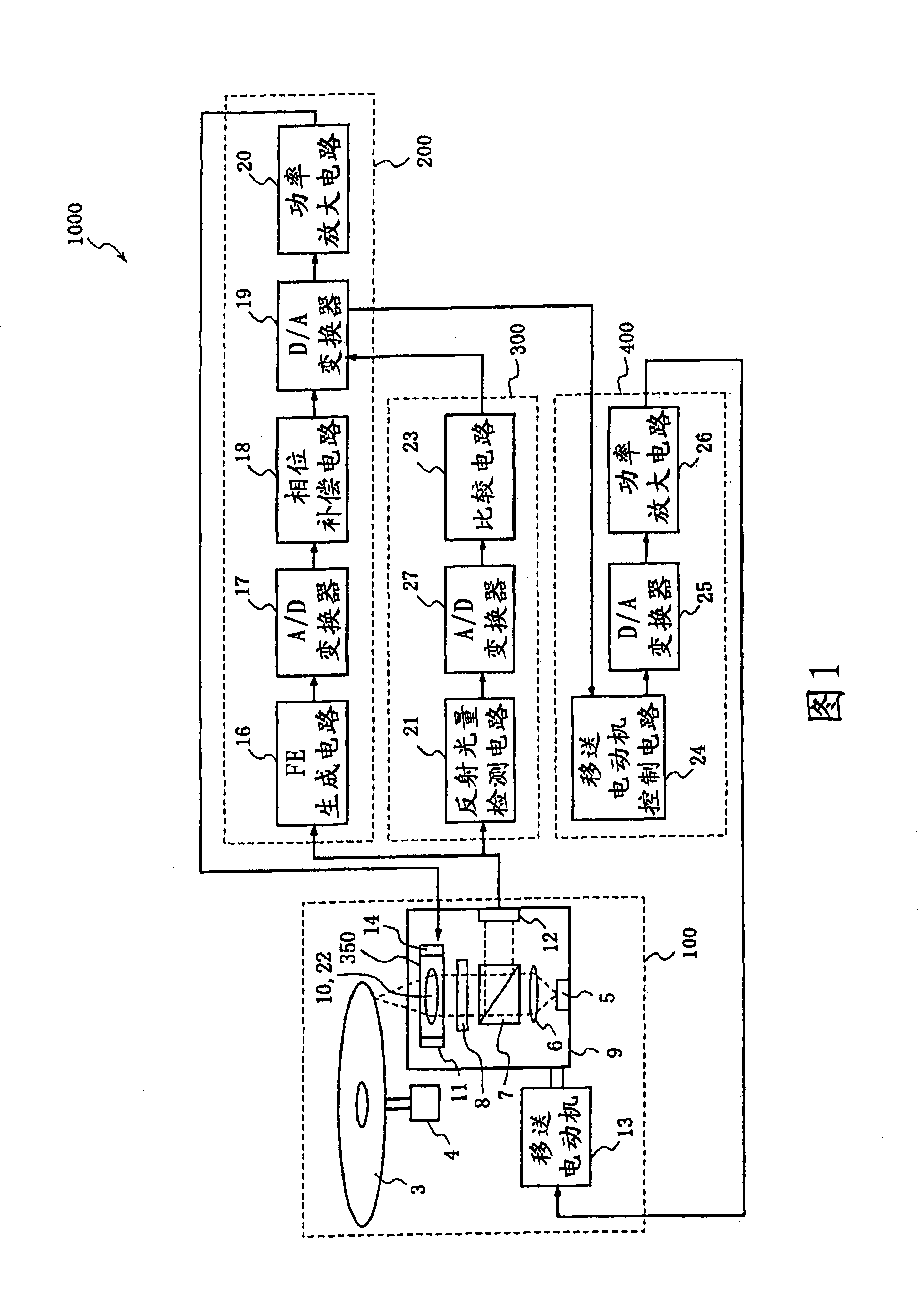
[0149] FIG. 1 shows a configuration diagram of an optical head transfer device 1000 according to Embodiment 1 of the present invention.

[0150] The optical head transfer device 1000 according to Embodiment 1 can be divided into four modules for its constituent elements. That is, an optical disc / optical head module 100 for irradiating a light beam to an optical disc and for receiving light from the optical disc; a focus control module 200 for realizing focus control; a focus abnormality detection module 300 for detecting an abnormality of the focus control system; And a transfer system drive module 400 for controlling the transfer motor for transferring the optical head.

[0151] Hereinafter, the configuration and operation of each of the modules 100 , 200 , 300 , and 400 will be described.

[0152] ·Disc / optical head module 100

[0153] The optical disc / optical head module 100 includes: an optical disc 3 as an information recording medium; a disc motor 4 made of, for exampl...

Embodiment approach 2

[0191] Next, an optical head transfer device 2000a according to Embodiment 2 of the present invention will be described with reference to FIG. 5( a ).

[0192] The second embodiment is equipped with a displacement control system for detecting the radial displacement of the optical disk 3 of the movable part 2 and reducing the displacement of the movable part 2. Compared with the non-action state, the acceleration of the transfer system is increased. Therefore, in order to realize this, a displacement amount control module 500 is provided. In addition, a part of the function of the transfer motor control circuit 59 differs from Embodiment 1. As shown in FIG. In FIG. 5( a ), other structures are the same as those in FIG. 1 .

[0193] Hereinafter, the displacement amount control module 500 will be described.

[0194] The displacement amount control module 500 for performing this displacement amount control includes brightness level detection circuits 50, 57, A / D converters 52, 5...

Embodiment approach 3

[0220] Next, an optical head transfer device 3000 according to Embodiment 3 of the present invention will be described with reference to FIG. 9 .

[0221] In Embodiment 3, a focus control state adjustment system for adjusting the control state of the focus control system is provided according to the displacement amount of the movable part 2 in the tracking direction, and the displacement of the movable part 2 in the tracking direction is used to correct the change. The amplitude and offset of the focus error signal.

[0222] In order to achieve this purpose, Embodiment 3 is provided with a focus control state adjustment module 600 . In FIG. 9 , the other configurations are the same as those in FIG. 5( a ) used in the second embodiment.

[0223] The focus control state adjustment module 600 includes a subtraction circuit 70 , a multiplication circuit 71 , an offset table 72 , and a gain table 73 .

[0224] The subtraction circuit 70 subtracts the output signal of the offset t...


PUM

PropertyMeasurementUnit
thicknessaaaaaaaaaa
thicknessaaaaaaaaaa

Abstract

When an optical head is carried in a radial direction of an optical disc, an optical head is first carried at a speed profile with a large acceleration. When abnormality is detected by an abnormality detecting circuit for detecting abnormality of a focus control system, the optical head is carried again at a speed profile with a small acceleration, so that a movable portion of a lens actuator is prevented from colliding with a fixed portion in the case the optical head is carried in the radial direction of the optical disc. Thus, an optical head carrying device, an integrated circuit for an optical head carrying device, a focusing lens driving device and an integrated circuit for a focusing lens driving device are provided to prevent increase in a starting-up time of the device and a lowering of a data reading speed from the optical disc.

Description

technical field [0001] The present invention relates to an optical head transfer device for transferring an optical head for reproducing or recording information to the radial direction of an optical disc in an optical disc device for reproducing information from or recording information on an optical disc, and an integrated circuit of the optical head transfer device. Background technique [0002] A digital versatile disc (DVD) is known as an optical disc capable of recording large-capacity data because it can record digital information at a recording density approximately six times that of a compact disc (CD). In recent years, along with the increase in the amount of information to be recorded on an optical disc, an optical disc with a further larger capacity has been demanded. In order to increase the capacity of an optical disc, it is necessary to increase the recording density of information by reducing the light spot formed by light irradiated on the optical disc when ...

Claims


Application Information

Patent Timeline
Patent Type & Authority Applications(China)
IPC IPC(8): G11B7/085G11B7/135G11B7/095
CPCG11B7/0945G11B2007/0006G11B7/08529
Inventor 山田真一石桥弘茂
Owner PANASONIC CORP
Why Eureka
Try Eureka