Sensor interface with integrated current measurement

Inactive Publication Date: 2009-03-19
ROBERT BOSCH GMBH
View PDF9 Cites 8 Cited by
  • Summary
  • Abstract
  • Description
  • Claims
  • Application Information

AI Technical Summary

Benefits of technology

[0024]Such a configuration of the control and evaluation apparatus makes it possible to connect different sensor unit

Problems solved by technology

Because of production tolerances, however, it is impossible to obtain sensor units PAS that generate exactly reproducible currents IPAS as a function of a measured signal (e.g. an acceleration signal).
This results in considerable complexity in terms of circuit engineering, thereby disadvantageously increasing the cost of the entire circuit assemblage.
It is critical In safety-relevant applications, moreover, if measuring resistor MW must be exchanged along with sensor unit PAS, since errors in allocating measuring resistor MW to sensor unit PAS can easily occur.
A further disadvantage with the conventional sensor evaluation app

Method used


Image

  • Sensor interface with integrated current measurement
  • Sensor interface with integrated current measurement
  • Sensor interface with integrated current measurement

Examples


Embodiment Construction

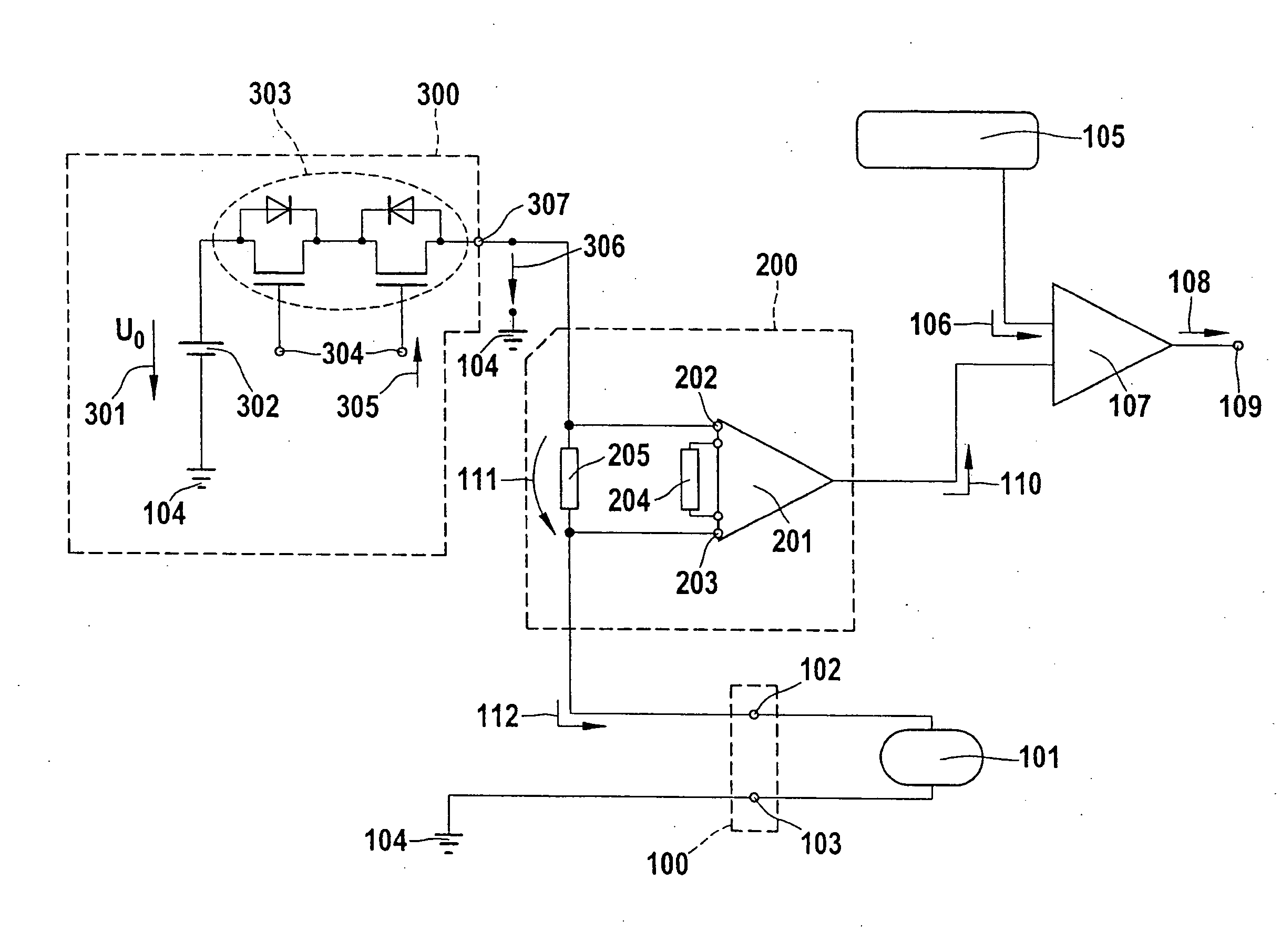
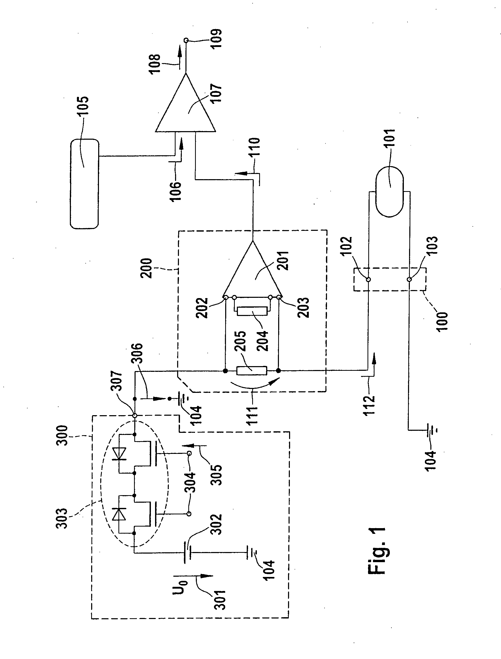
[0028]FIG. 1 is a block diagram of a control and evaluation apparatus according to the present invention for controlling a sensor unit 101 and for evaluating sensor signals 112 that are furnished by sensor unit 101 as a function of a measured variable. Sensor unit 101 is connected via an interface unit 100 to the remainder of the circuit assemblage. According to the present invention, interface unit 100 makes available a first sensor terminal 102 and a second sensor terminal 103. Sensor unit 101 is connected via second sensor terminal 103 to ground 104. In addition to ground terminal 103, only first sensor terminal 102 is necessary for the connection of sensor unit 101.

[0029]It should be noted—although this is not illustrated in FIG. 1—that the remainder of the circuit assemblage, except for sensor unit 101 and interface unit 100, can be made available as an integrated circuit assemblage.

[0030]A reference number 300 designates an energy supply unit, and a reference number 200 design...


PUM


Abstract

The invention creates a control and evaluation apparatus for different sensor units, having: a stabilized supply unit for supplying the sensor unit with electrical energy; an amplifier device for amplifying a sensor signal generated by the sensor unit, which signal is delivered to the amplifier device as an input signal, and for outputting a measured signal dependent on the sensor signal; and an output unit for outputting the amplified sensor signal as an output signal. The amplifier device contains an integrated measuring resistor for measuring a voltage drop produced by the sensor signal, the voltage drop being delivered to the amplifier device as the input signal. In addition, in a comparator unit downstream from the amplifier device, the measured signal is compared with a definable threshold value, the threshold value being adjustable as a function of the sensor unit being used.

Description

FIELD OF THE INVENTION[0001]The present invention relates in general to a sensor interface for transferring sensor signals, a sensor unit, furnishing the sensor signals, being connectable via an interface to a control and evaluation unit. The present invention relates in particular to a control and evaluation apparatus having a sensor interface for controlling sensor units and for evaluating the signals furnished by the sensor units, which apparatus has a simple configuration.[0002]The present invention relates specifically to a control and evaluation apparatus for a sensor device having: an energy supply unit for supplying the sensor unit with electrical energy; an amplifier device for amplifying a sensor signal generated by the sensor unit and for outputting an amplified measured signal dependent on the sensor signal; and an output unit for outputting the amplified sensor signal as an output signal.BACKGROUND OF THE INVENTION[0003]Conventional sensor units are connected via termin...

Claims


Application Information

Patent Timeline
IPC IPC(8): G01D18/00
CPCB60R21/0132G01R19/16571G01P21/00G01P15/00G01R19/16566
Inventor SCHUMACHER, HARTMUTKARNER, RUEDIGER
Owner ROBERT BOSCH GMBH
Why Eureka
Try Eureka