Large effective area fiber with graded index GE-free core

a technology of ge-free core and effective area, applied in the field of optical fibers, can solve the problems of signal degradation, non-linear optical effect of high-power systems, and high-power systems that suffer from non-linear optical effects

Active Publication Date: 2011-04-19
CORNING INC
View PDF7 Cites 64 Cited by
  • Summary
  • Abstract
  • Description
  • Claims
  • Application Information

AI Technical Summary

Problems solved by technology

High power systems often suffer from non-linear optical effects, including self-phase modulation, four-wave-mixing, cross-phase modulation, and non-linear scattering processes, all of which can cause degradation of signals in high powered systems.
In addition, other optical fiber attributes, such as attenuation, are a major contributing factor to the degradation of the signal.
Generally, an optical waveguide fiber having a large effective area (Aeff) reduces non-linear optical effects, including self-phase modulation, four-wave-mixing, cross-phase modulation, and non-linear scattering processes, all of which can cause degradation of signals in high powered systems.
On the other hand, an increase in effective area of an optical waveguide fiber typically results in an increase in macrobending induced losses which attenuate signal transmission through a fiber.
Furthermore, attenuation can be a major contributing factor to the degradation of the signal in large effective area fibers.

Method used


Image

  • Large effective area fiber with graded index GE-free core
  • Large effective area fiber with graded index GE-free core
  • Large effective area fiber with graded index GE-free core

Examples


embodiment (

Embodiment(s) of the Invention

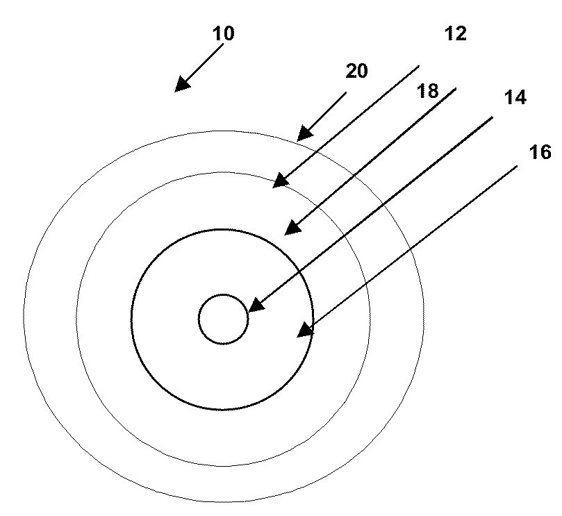
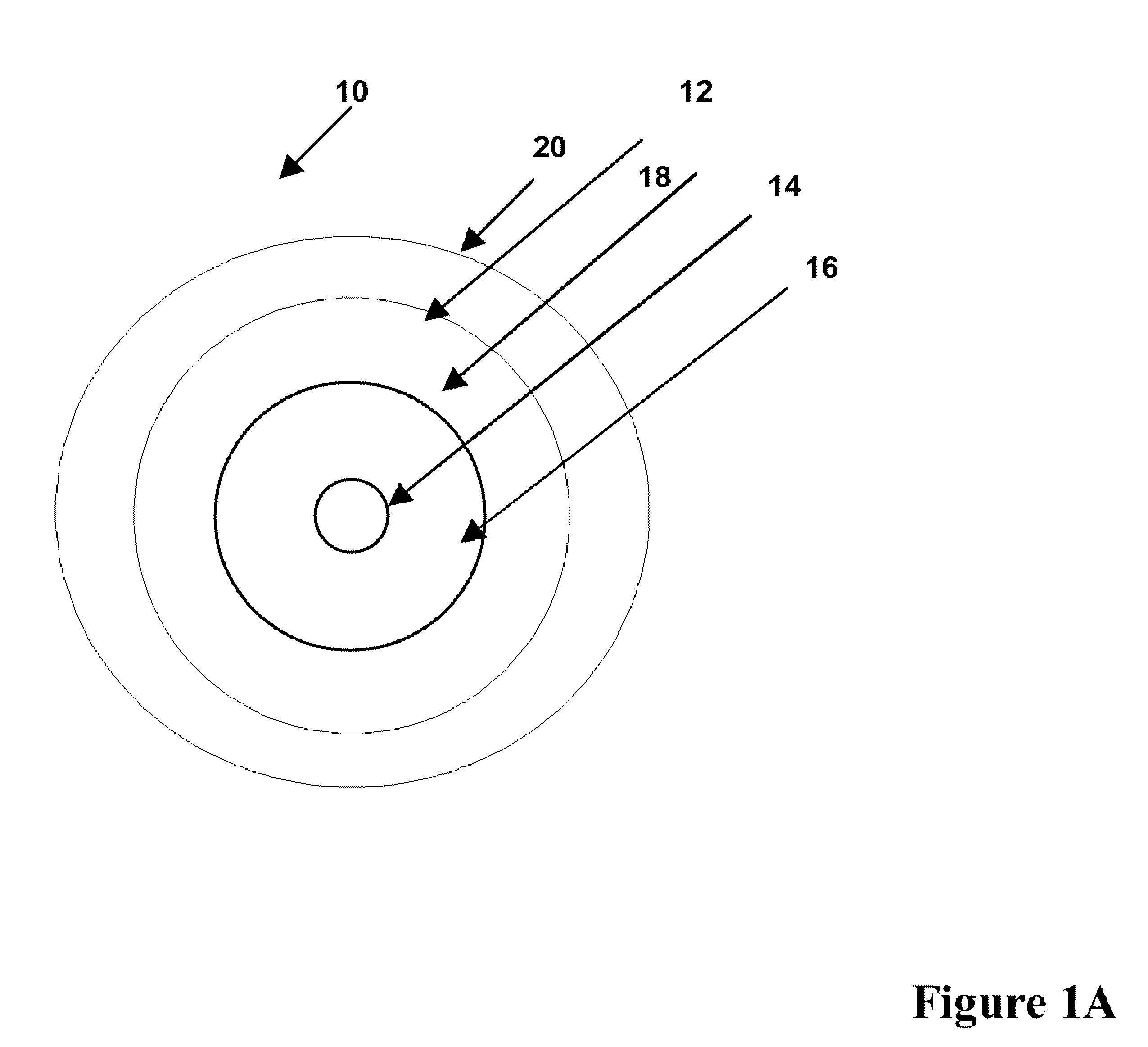
[0035]Reference will now be made in detail to the present embodiment(s) of the invention, examples of which are illustrated in the accompanying drawings. Whenever possible, the same reference numerals will be used throughout the drawings to refer to the same or like parts. One embodiment of the optical fiber of the present invention is shown in FIG. 1A, and is designated generally throughout by the reference numeral 10. The waveguide fiber 10 includes a core 12 having an effective area of about 100 μm2 or more at a 1550 nm wavelength (for example, 100 μm2 to 160 μm2, or 105 μm2 to 150 μm2, or 120 to 140 μm2 at a 1550 nm wavelength), and α value 1.5≦α≦10, and a cladding 20 surrounding the core. A typical range of α values in the exemplary fibers described herein is 1.5 to 4, for example 1.8≦α≦3. The exemplary refractive index profile (relative refractive index delta, vs. radius) of this fiber shown schematically (solid line) in FIG. 1B.

[0036]The core 12 ...


PUM


Abstract

According to some embodiments an optical waveguide fiber comprises (i) a Ge free core having an effective area of 100 μm2to 150 μm2, at 1550 nm wavelength, said core comprising: a) a central core region extending radially outwardly from a centerline to a radius r1, and having a relative refractive index percent profile Δ1(r) in % measured relative to pure silica, wherein −0.1%≦Δ1(r)≦0.12%, wherein the central core region has a maximum relative refractive index percent, Δ1MAX; (b) a first annular core region surrounding and directly adjacent to the central core region, having an α value 1.5≦α≦10, and extending to an outer radius r2, wherein 6 μm≦r2≦10 μm, and having a relative refractive index percent profile, Δ2(r) in % measured relative to pure silica, a minimum relative refractive index Δ2MIN, a maximum relative refractive index Δ2MAX and the relative refractive index measured at a radius r=2 μm, wherein 0.45≦Δ2≦0; −0.25≧Δ2MIN≧−0.45 and Δ1MAX≧Δ2(r=2 μm); (c) a fluorine doped second annular region surrounding and directly adjacent to the first annular core region and extending to a radius 20 μm≦r3≦30 μm and having a negative relative refractive index percent profile, Δ3(r) in %, measured relative to pure silica, with a minimum relative refractive index percent Δ3MIN and −0.5%<Δ3MIN<−0.25%; and Δ3MIN≦Δ2MIN; (ii) a cladding surrounding the core and having a relative refractive index percent Δ4(r) in % measured relative to pure silica and a minimum refractive index delta Δ4MIN, and −0.4%<Δ4<−0.2%; wherein the relative refractive index profile of the optical fiber is selected to provide attenuation of no more than 0.17 dB / km at the 1550 nm wavelength.

Description

FIELD OF THE INVENTION[0001]The present invention relates generally to optical fibers, and particularly to large effective area optical fibers with pure silica core and low attenuation.TECHNICAL BACKGROUND[0002]Optical amplifier technology and wavelength division multiplexing techniques are typically required in telecommunication systems that provide high power transmissions for long distances. The definition of high power and long distances is meaningful only in the context of a particular telecommunication system wherein a bit rate, a bit error rate, a multiplexing scheme, and perhaps optical amplifiers are specified. There are additional factors, known to those skilled in the art, which have impacted upon the definition of high power and long distance. However, for most purposes, high power is an optical power greater than about 10 mW. High power systems often suffer from non-linear optical effects, including self-phase modulation, four-wave-mixing, cross-phase modulation, and no...

Claims


Application Information

Patent Timeline
Patent Type & Authority Patents(United States)
IPC IPC(8): G02B6/028
CPCG02B6/02019G02B6/02266G02B6/0365G02B6/0286G02B6/02395G02B6/028G02B6/036
Inventor BICKHAM, SCOTT ROBERTSONKHRAPKO, ROSTISLAV RADIEVICHMISHRA, SNIGDHARAJ KUMAR
Owner CORNING INC
Why Eureka
Try Eureka