Top drive drilling apparatus

a drilling apparatus and top drive technology, applied in the direction of drilling pipes, rotary drilling, borehole/well accessories, etc., can solve the problems of affecting the operation of the drilling machine, and requiring complete disassembly of the machine, so as to reduce the repair time and increase the repair interval

Active Publication Date: 2011-04-26
MHWIRTH
View PDF12 Cites 21 Cited by
  • Summary
  • Abstract
  • Description
  • Claims
  • Application Information

AI Technical Summary

Benefits of technology

[0009]By repeal of function for the drilling machine the basis of income for the drilling vessel is annulled. For this reason the repair time for a drilling machine is very critical, and the present invention has as a substantial object to reduce the repair time and increase the repair intervals.
[0016]Thus it is to be understood that the architecture of the machine is substantially changed relative to the prior art. In addition to the advantages as described above, the machine is arranged and adapted for rapid replacement of the main components. In order to accomplish this, which also is a substantial difference that distinguish the new drilling machine concept from the prior art, is the subdivision of the construction elements of the machine, i.e. modules which with a minimum of effort is able to separate the machine into larger components with the aim to reduce the time for disassembly / assembly during maintenance work and repair.
[0021]As it will be understood, the mutual interconnection of the component modules is now focused around the load frame. This means that previous complicated operations for disassembly and maintenance gets substantially reduced extent. This is further visualized in table 2 which shows the interface between the different components of the new drilling machine.

Problems solved by technology

A breakdown in any of these complicated mechanical components entails complete disassembly of the machine.
This takes a long time to maintain and represents downtime for the drilling operations of the rig.

Method used


Image

  • Top drive drilling apparatus
  • Top drive drilling apparatus
  • Top drive drilling apparatus

Examples


Embodiment Construction

[0054]Table 1 on side 26 shows an oversight over which components make interface with each other in the prior art drilling apparatus, and tell something about the number of components that need to be disassembled in order to create access during maintenance.

[0055]Table 2 on side 27 shows an oversight over those components in the new drilling apparatus according to the invention that have a common interface.

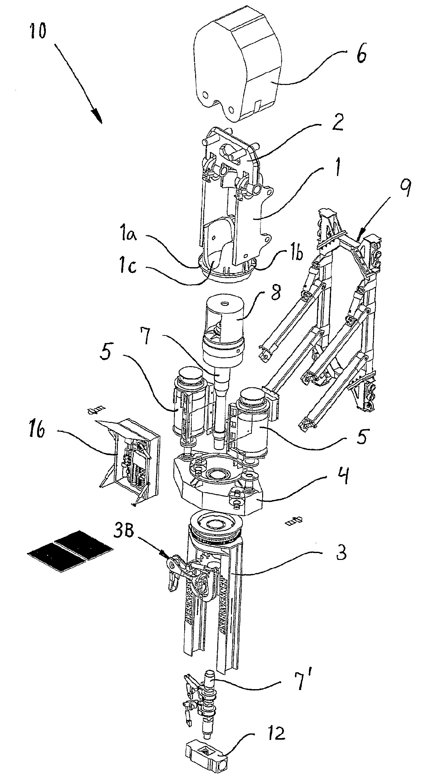
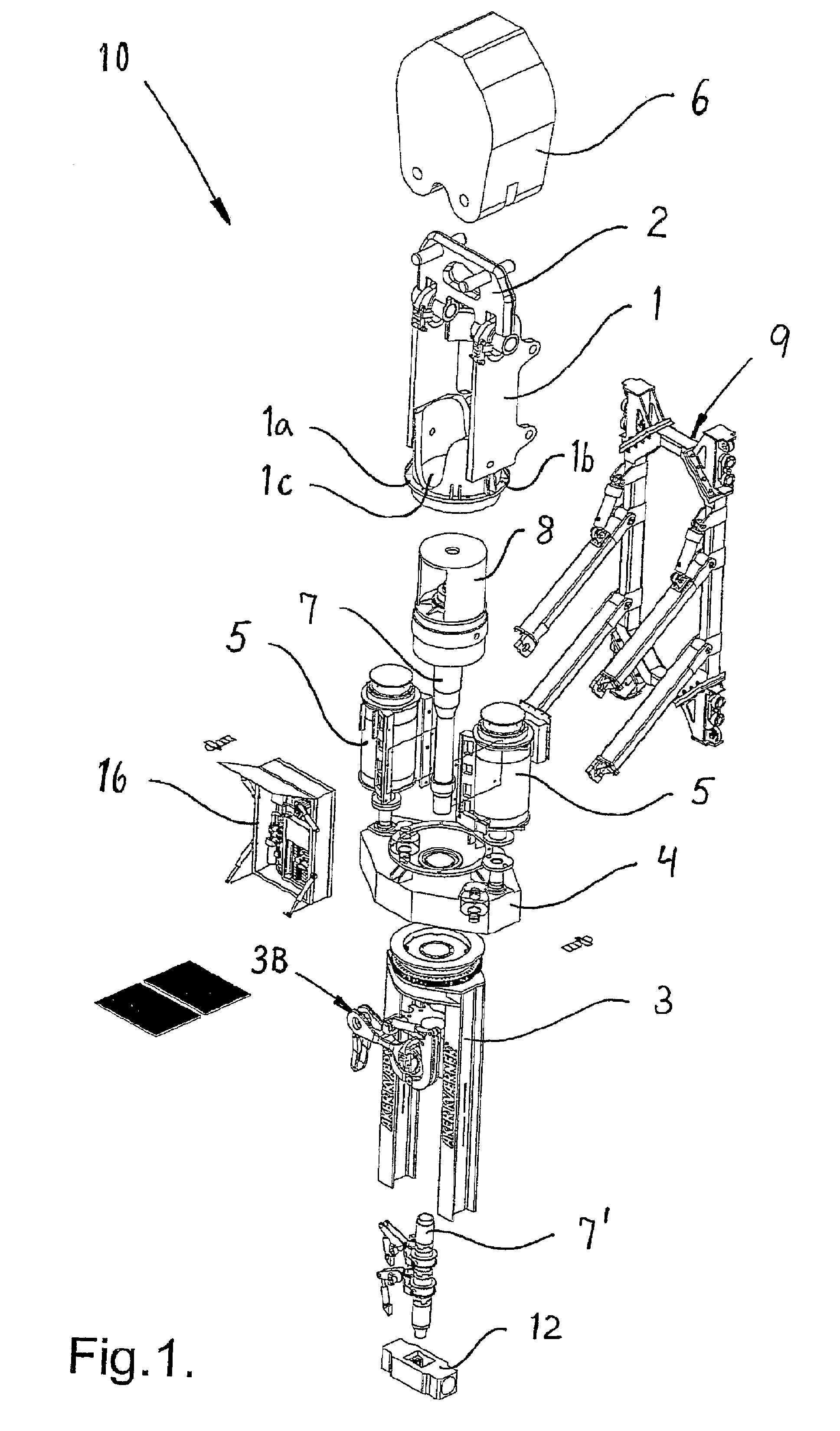
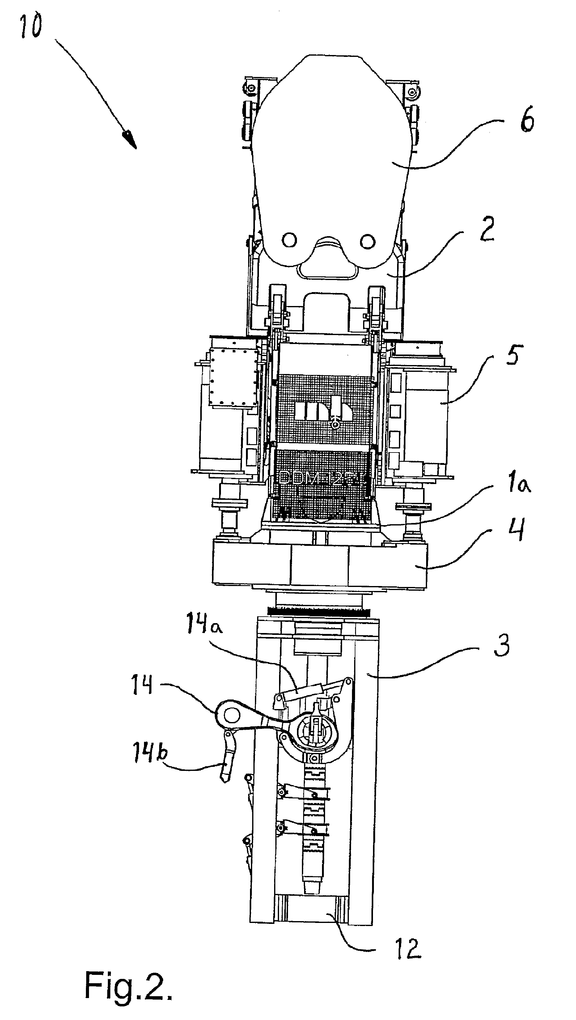
[0056]Reference is now made to FIG. 1 which shows the new modularly constructed drilling machine 10 with the parts separated from each other, and FIG. 2-4 that show the assembled drilling machine 10. The drilling machine 10 is designed to be suspended in a pulley block 6 in a drawworks arranged in a derrick (not shown) on board a vessel performing offshore drilling activity. The drilling machine 10 is guided by a dolly 9 running along rails attached to the derrick. The drilling machine 10 turns drill pipes around a drilling axis to drill an oil and gas well in the sea bed. With re...


PUM


Abstract

A well drilling apparatus (10′) (top drive) designed to be suspended from a travelling block (6′) in a drawworks and laterally supported by a dolly (9′) running together with the well drilling apparatus along tracks or rails fixed to a derrick. The drilling apparatus (10′) comprises at least one driving motor (5′), one power transmission (4′) powered by the at least one driving motor (5′), a drive shaft (70) driven from the power transmission (4′) and designed to be connected to a drill string, load transferring means, and a torque arresting device (3′) fixed to and depending from the power transmission (4′). The load transferring means is in the form of a load frame module (1′) that relieves the drive shaft (70) and the power transmission (4′) at the same time as the load frame module (1′) forms a central component module that the other main components of the well drilling apparatus are releasable connected to.

Description

CROSS-REFERENCE TO RELATED APPLICATIONS[0001]This application is the U.S. national phase of International Application No. PCT / NO2006 / 000457, filed 4 Dec. 2006, which designated the U.S. and claims priority to Norway Application No. 2005 5709, filed 2 Dec. 2005, the entire contents of each of which are hereby incorporated by reference.BACKGROUND OF THE INVENTION[0002]The present invention relates to a well drilling apparatus designed to be suspended from a traveling block in a drawworks and laterally supported by a dolly running together with the well drilling apparatus along tracks or rails attached to a derrick, which well drilling apparatus comprises at least one driving motor, one power transmission powered by the at least one driving motor, a drive shaft driven from the power transmission and designed to be connected to a drill string, load transferring means, and a torque arresting device attached to and depending from the power transmission.[0003]Well drilling machines that ar...

Claims


Application Information

Patent Timeline
Patent Type & Authority Patents(United States)
IPC IPC(8): E21B19/00E21BE21B3/02
CPCE21B3/02E21B3/022E21B19/00
Inventor RUDSHAUG, BJORNHAVERSTAD, DAG
Owner MHWIRTH
Why Eureka
Try Eureka