Stuffing box apparatus

a stuffing box and apparatus technology, applied in mechanical equipment, sealing/packing, borehole/well accessories, etc., can solve the problems of poor sealing performance, easy damage to the polish rod or the housing of the stuffing box, and fast wear of seal types, so as to improve reliability, improve wear performance, and be easily replaced

Active Publication Date: 2011-04-26
KK TOPCON
View PDF15 Cites 19 Cited by
  • Summary
  • Abstract
  • Description
  • Claims
  • Application Information

AI Technical Summary

Benefits of technology

[0014]By providing wiper members in sealing engagement with the polish rod in addition to separate sealing members, sealing is provided with improved reliability and improved wear performance as compared to the prior art. By locating the wiper member in a counter bore within the bushing at the lower end of the housing, the wiper member can be readily replaceable while being optimally located below the packing seals for extending the life of the sealing members. The counter bore in the bushing which receives the wiper member therein provides a sealing function to the bushing in addition to centering the polish rod relative to the housing of the stuffing box.

Problems solved by technology

Due to the compression required to effect a good seal, it is common for these types of seals to wear quickly and to lose their sealing ability due to overheating from relative movement of the polished rod against the packed seals.
When relying solely on such packing type seals as noted in the cited examples above, poor sealing performance is achieved and there is concern for damage to the polish rod or the housing of the stuffing box due to debris entering the stuffing box due to the movement of the polish rod.
While the scrapers assist in preventing large debris from entering into the housing of the stuffing box, the configuration of the scrapers provide no assistance to sealing against the polish rod for containing the pressure in the well.

Method used


Image

  • Stuffing box apparatus
  • Stuffing box apparatus
  • Stuffing box apparatus

Examples


Embodiment Construction

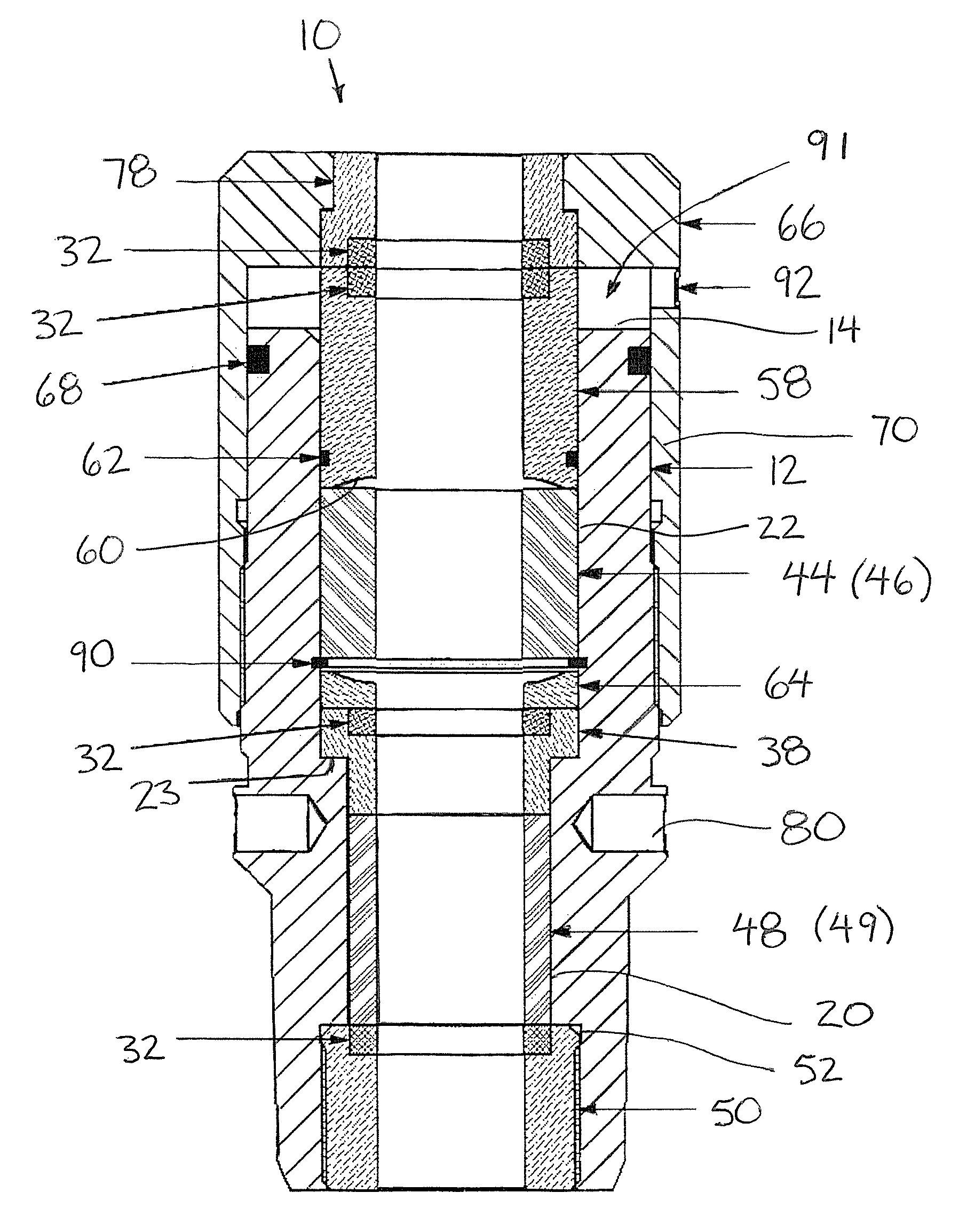
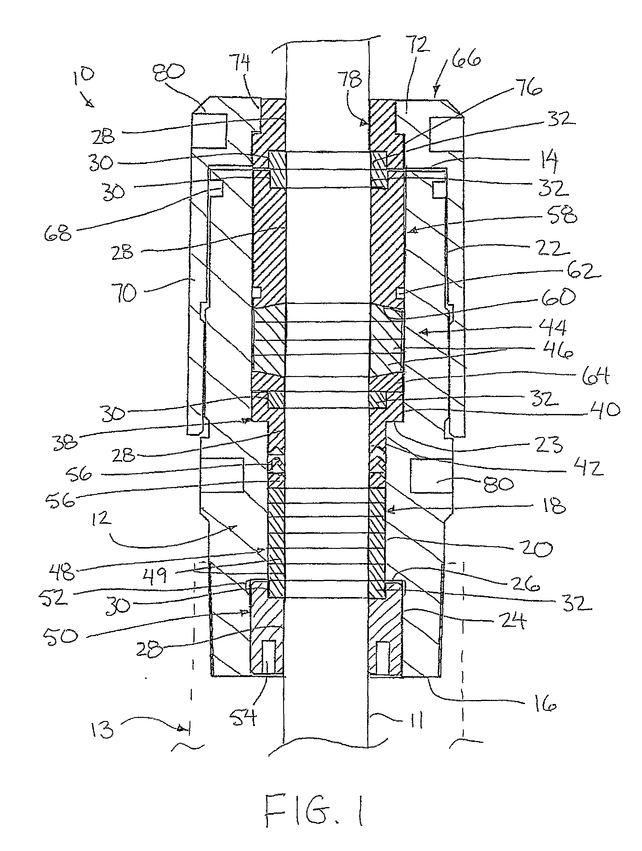
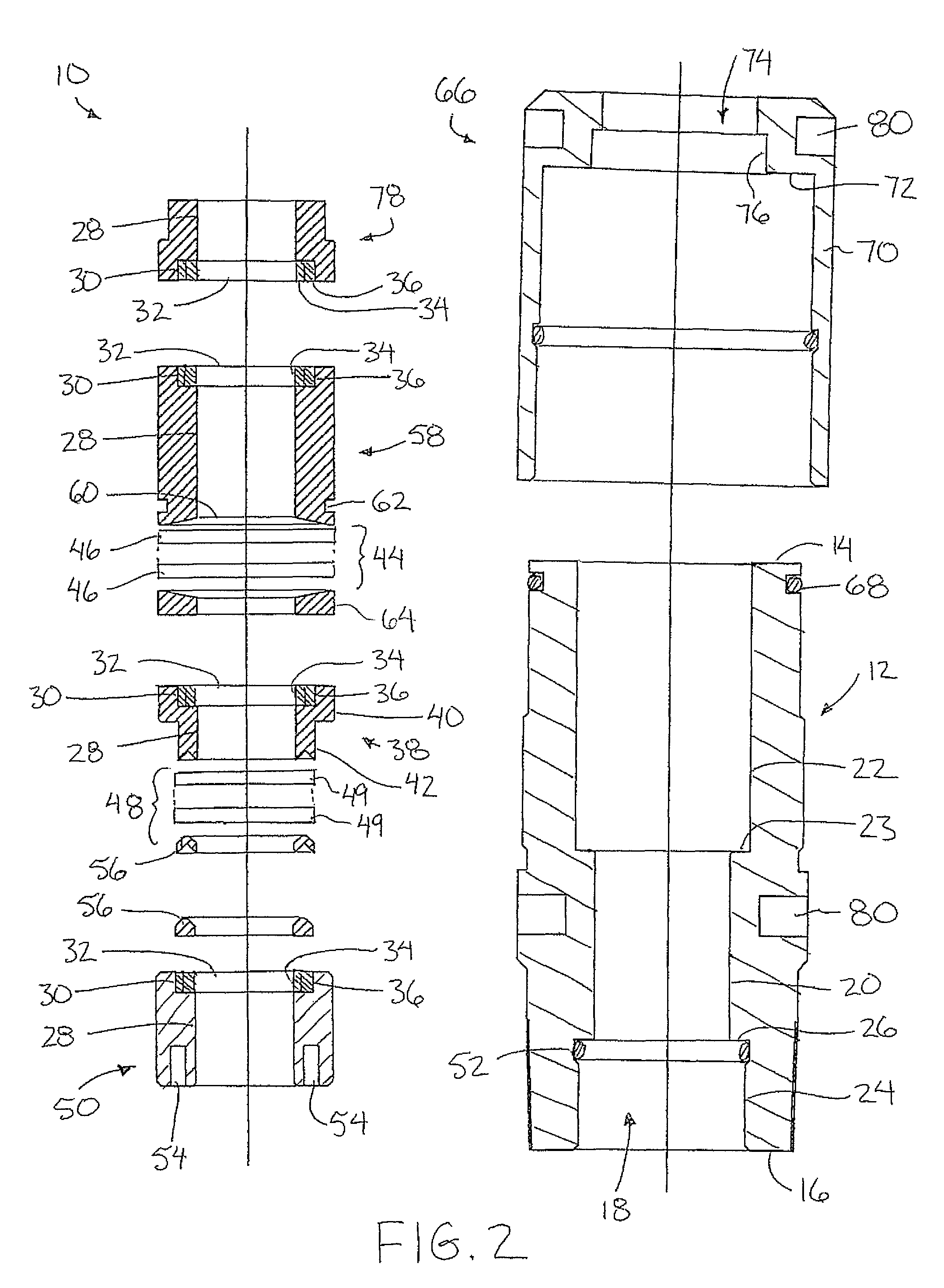
[0038]Referring to the accompanying figures there is illustrated a stuffing box apparatus generally indicated by reference 10. The apparatus 10 is particularly suited for sealing between the polish rod 11 and the well head of a hydrocarbon production well 13. The polish rod 11 has a constant diameter and is arranged to extend from the well in a conventional manner.

[0039]The apparatus 10 comprises a tubular housing 12 which extends in an axial direction between a top end 14 and a bottom end 16 thereof. The bottom end 16 of the housing is configured for mating and sealing connection to the well 13.

[0040]A bore 18 extends axially through the housing for receiving the polish rod of the well therethrough. The bore diameter is arranged to be greater than the diameter of the rod along a full length of the tubular housing so that an annular gap is defined between the polish rod and the surrounding inner surface of the bore 18 along the full length of the housing such that sealing material c...


PUM


Abstract

A stuffing box apparatus for sealing between a polish rod in a hydrocarbon production well comprises a tubular housing arranged for connection to the well which has a bore therethrough to receive the polish rod. Sealing members are supported in the bore of the housing in an upper stack and a lower stack of smaller outer diameter separated by an intermediate bushing. An upper bushing compresses the upper stack against the intermediate bushing. The lower bushing fixes the lower stack against the bottom of the intermediate bushing. Each of the bushings includes a counter bore formed at one end which receives a wiper member arranged for sealing engagement between the bushing and the polish rod.

Description

[0001]This application claims the benefit under 35 U.S.C. 119(e) of U.S. provisional application Ser. No. 61 / 030,612, filed Feb. 22, 2008.FIELD OF THE INVENTION[0002]The present invention relates to a stuffing box for sealing between a wellhead and a polish rod received therethrough.BACKGROUND[0003]In a well pumping apparatus, it is customary to employ a stuffing box at the wellhead to prevent oil, water and gases produced under pressure by the pumping apparatus from escaping into the atmosphere. Generally, the stuffing box is disposed in surrounding relation to the polished rod in order to guide or center the polished rod for vertical reciprocal movement or for rotation without the escape of produced liquids or gases. Typically, the stuffing box is able to prevent the loss of produced liquids and gases by utilization of a series of packing coils which are compressed within the stuffing box by bearings at opposite ends of the coils and are squeezed or otherwise forced against the co...

Claims


Application Information

Patent Timeline
Patent Type & Authority Patents(United States)
IPC IPC(8): E21B33/08
CPCE21B33/08F16J15/184E21B43/126
Inventor TOPOROWSKI, BARTONHOCKLEY, DALEBATEMAN, PERRY
Owner KK TOPCON
Why Eureka
Try Eureka