
Suspended load ergonomic backpack

a backpack and ergonomic technology, applied in the field of ergonomic backpacks, can solve the problems of ineffective small wheels, difficult to move at high speeds, and small backpacks, etc., and achieve the effects of reducing the metabolic rate of carrying, facilitating movement, and facilitating movemen

Active Publication Date: 2011-04-26
LIGHTNING PACKS
View PDF71 Cites 20 Cited by
  • Summary
  • Abstract
  • Description
  • Claims
  • Application Information

AI Technical Summary

Benefits of technology

Enables carrying heavier loads with reduced metabolic cost and decreased risk of injury, allowing for faster and more comfortable transport of loads, particularly beneficial for first responders, disaster relief workers, and athletes by minimizing joint stress and energy expenditure.

Problems solved by technology

On uneven terrain or in the wilderness, however, small wheels are ineffective.
Backpacks, however, have their own limitations.
These high, sometimes jarring, peak forces make it difficult to move at high speeds with large loads, and may also contribute to the muscular and orthopedic injury suffered by those carrying heavy weights relative to their body mass.
This downward force also leads to increased ground reaction force pushing up at the foot-ground contact, and thereby increases force on the joints.
In the case of running, the increased force puts very high forces on the joints resulting in orthopedic and muscle pain and injury.
A similar effect has been seen in soldiers with backpacks jumping out of trucks, during which the high forces incurred can lead to broken ankles.
The large weight of backpacks carried by children is well recognized to be a significant international public health problem, and reduction in dynamic forces may reduce muscle and orthopedic injury.
Furthermore, in some of these cases, the ability to carry equipment to the disaster / emergency site faster could be the difference between success and failure.

Method used


Image

  • Suspended load ergonomic backpack
  • Suspended load ergonomic backpack
  • Suspended load ergonomic backpack

Examples


embodiment

Running Backpack Embodiment

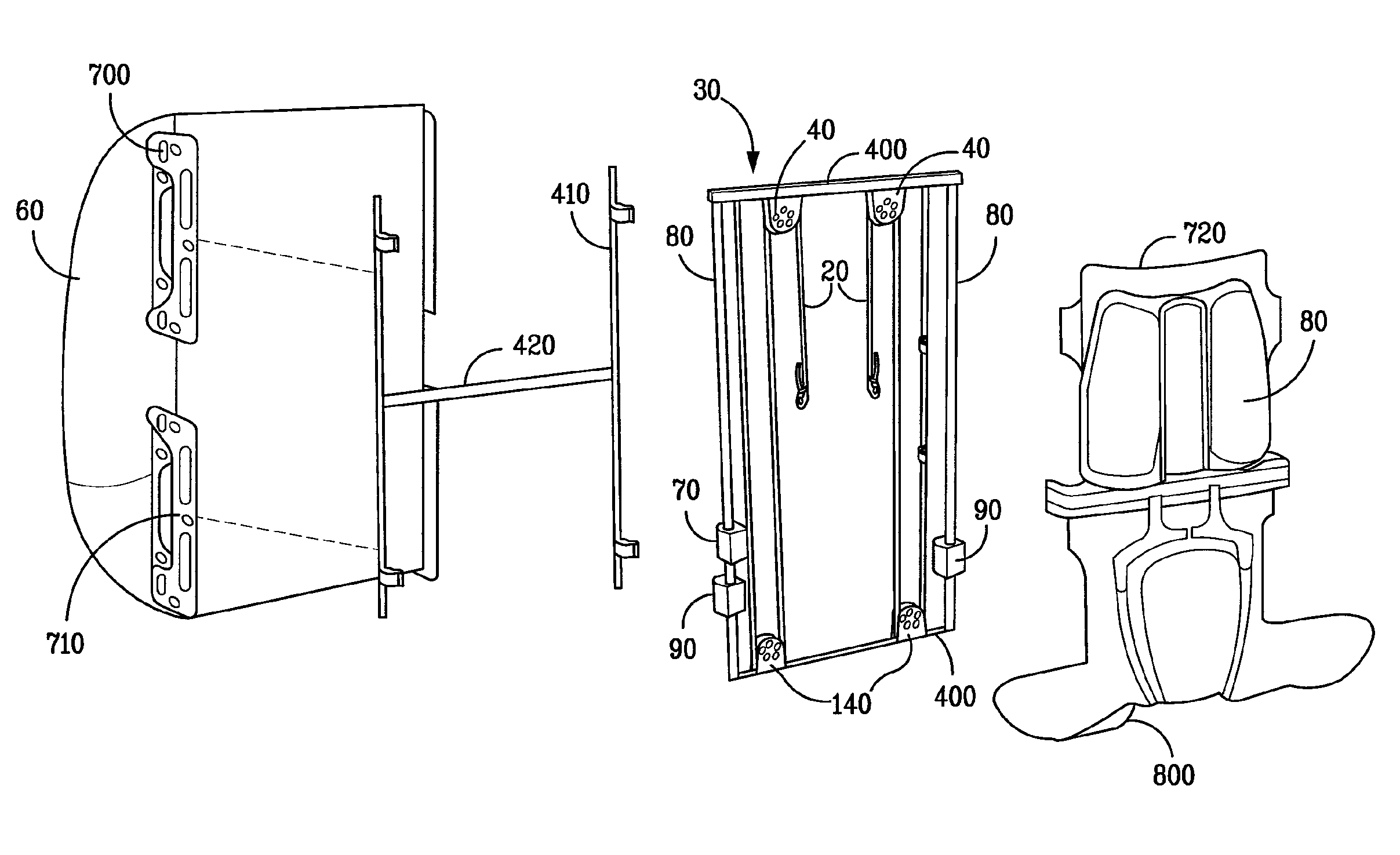
[0049]The principles illustrated above can be applied to any type of load carrying device in use for profession or sports. For example, it has become common for runners or long distance trekkers to run with backpacks carrying water, food, and potentially clothing. Running backpacks are generally made to attaching tightly to the body, hence the load must be accelerated on every step. However, if the load were suspended in accordance with the invention so that it stayed at nearly a constant vertical height and would not have to be accelerated on every step, then a significant reduction in forces would be achieved. To reduce such forces, the backpack of the embodiments of FIGS. 3-6 or 7 may be used with the addition of a frictional device to take out a bit more energy than is dissipated in the compliant coupling. For example, the embodiment of FIG. 8 shows the addition of a rack 300 and pinion 310 that drive a fan 320. Alternatively, as described in U.S. Pat....


PUM


Abstract

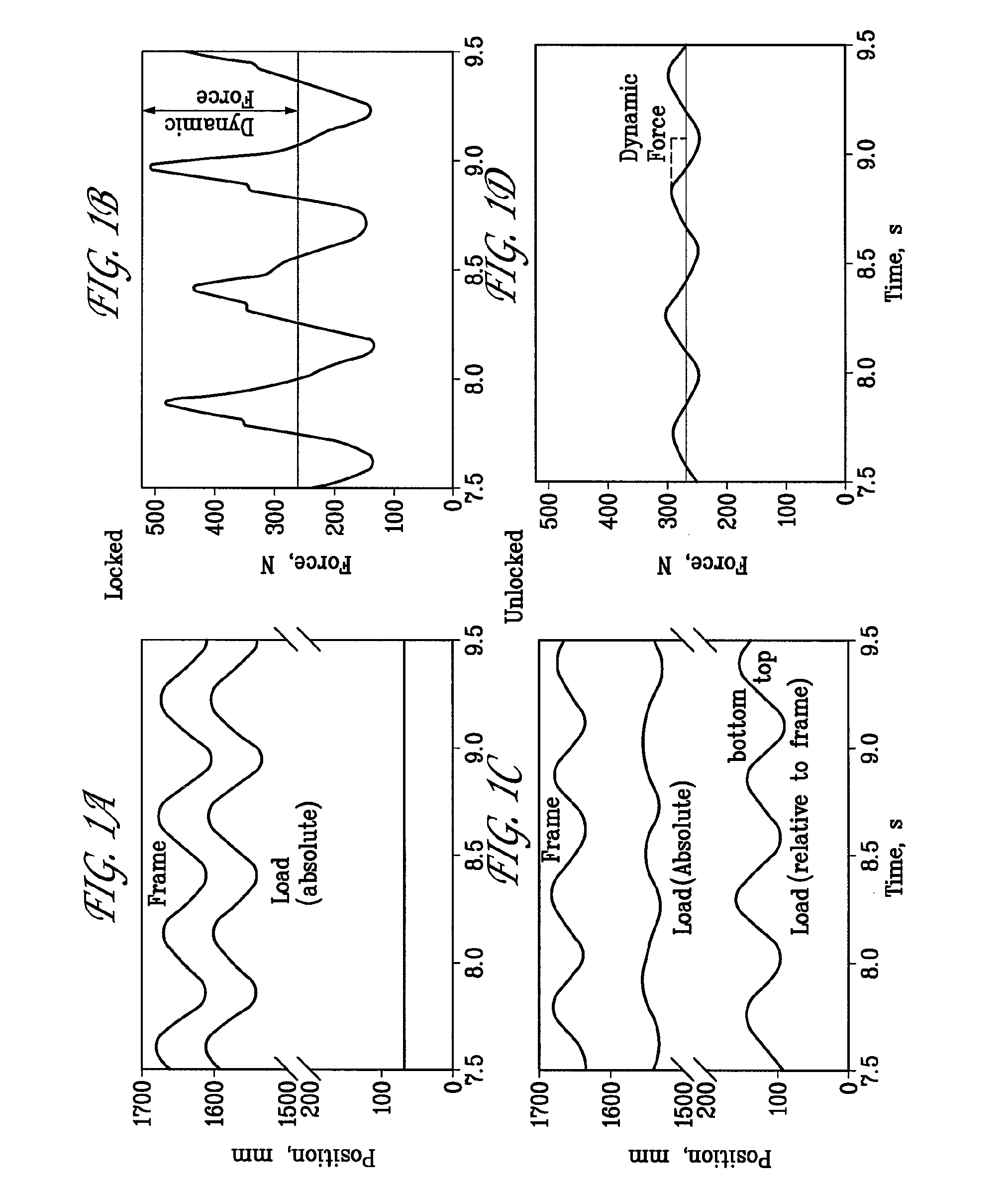
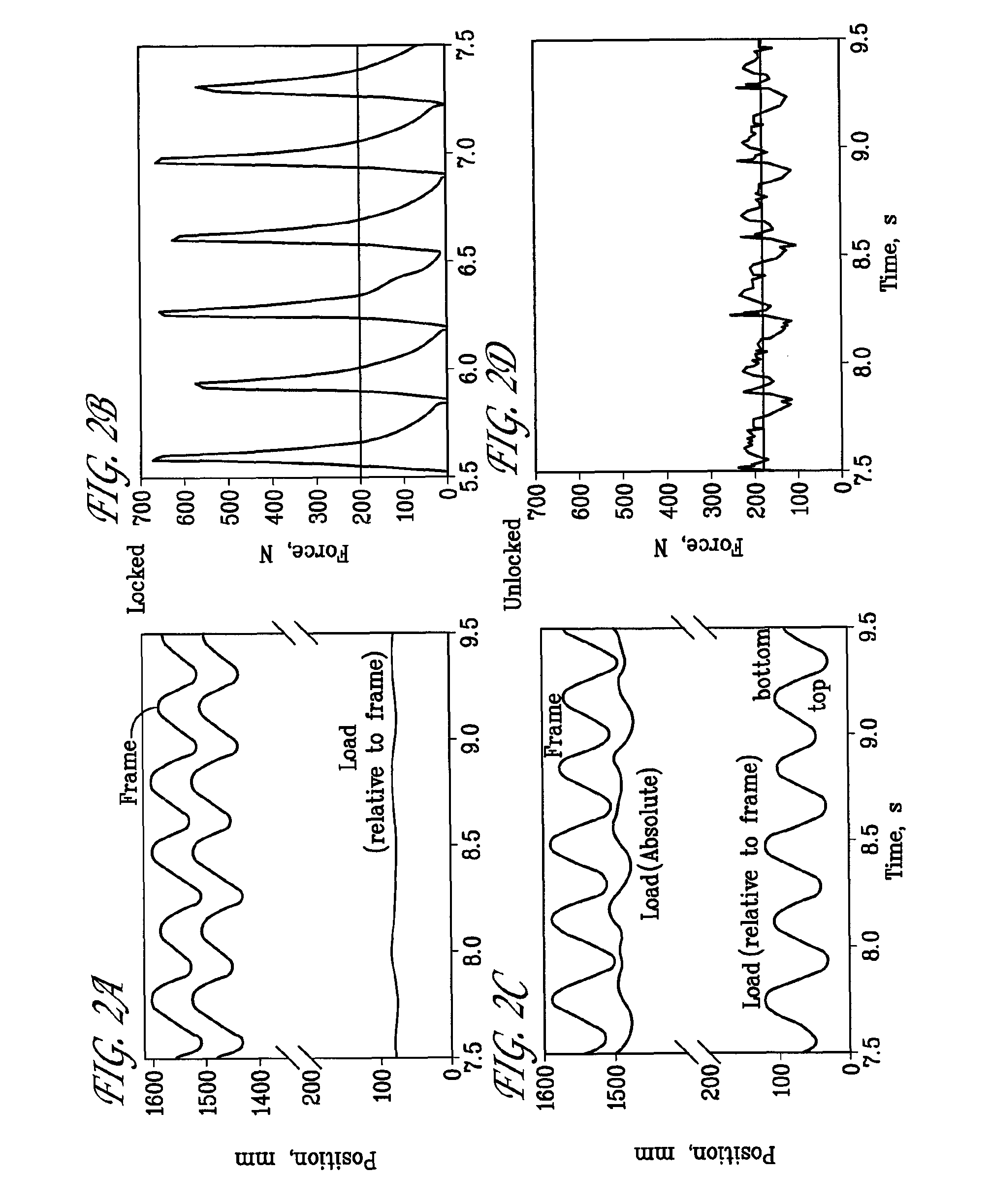
A suspended-load backpack designed to permit the load to move relative to the wearer during walking and running so that the large movements between the load and the wearer of the backpack reduce the fluctuations of vertical motion of the load with respect to ground. Because the hip (and thus the pack body) goes up a down a good deal during walking, a large relative movement between the wearer and the load reduces the absolute excursion of the load. This movement may be, in turn, transferred to a motor through, for example, a rack and pinion gear, to convert the mechanical movement to electrical or mechanical energy. Such movement of the suspended-load relative to the wearer also reduces the forces on the wearer's body while walking or running, thus reducing the likelihood of orthopedic injury. The suspended-load backpack includes a suspension system having a first portion connected to shoulder straps directly or through an interface and a second portion connected to the pack body and a compliant mechanism that permits the second portion of the suspension system and the pack body to move up and down relative to the first portion of the suspension system in accordance with a gait of the wearer of the backpack.

Description

CROSS-REFERENCE TO RELATED APPLICATIONS[0001]The present application claims priority under 35 U.S.C. §119(e) to U.S. Provisional Patent Application Ser. Nos. 60 / 875,092 and 60 / 875,238, filed Dec. 14, 2006, the contents of which are incorporated herein by reference. The present application is also a continuation-in-part application of U.S. patent application Ser. No. 11 / 056,849, filed Feb. 11, 2005, which is a divisional application of U.S. Ser. No. 10 / 803,112, filed Mar. 17, 2004, now U.S. Pat. No. 6,982,497, which, in turn, claims benefit to U.S. Provisional Patent Application Ser. No. 60 / 455,477, filed Mar. 17, 2003, the entire contents of which are herein incorporated by reference.STATEMENT REGARDING FEDERALLY SPONSORED RESEARCH OR DEVELOPMENT[0002]This invention was made with government support under N00014-03-1-0568 and N00014-06-M-0309 awarded by the Office of Naval Research and under Grant Nos. AR46125, AR38404 and R43HD55110 awarded by the National Institutes of Health. The ...

Claims


Application Information

Patent Timeline
Patent Type & Authority Patents(United States)
IPC IPC(8): A45F3/08
CPCA45F3/04F03G7/08F03G5/06A45F3/08F03G5/062
Inventor ROME, LAWRENCE CRUINA, ANDY L
Owner LIGHTNING PACKS
Learn More