One phase logic

a logic and phase technology, applied in the field of one phase logic, can solve the problems of limiting the rate at which data can be transmitted over the communication link, reducing power consumption, and not being able to eliminate portions of acknowledge circuitry

Active Publication Date: 2011-04-26
ACHRONIX SEMICON CORP
View PDF3 Cites 6 Cited by
  • Summary
  • Abstract
  • Description
  • Claims
  • Application Information

AI Technical Summary

Problems solved by technology

This would be an error.
The degree of mismatch in delay will limit the rate at which data can be transmitted over the communication link.
In some situations it may not be possible to eliminate portions of the acknowledge circuitry.
Implementing such circuits may result in reduced power consumption, reduced die area, and increased processing speed.

Method used


Image

  • One phase logic
  • One phase logic
  • One phase logic

Examples


Embodiment Construction

[0011]Example methods, systems and circuits for providing asynchronous one-phase logic operation, including a pipeline, will now be described. In the following description, numerous examples having example-specific details are set forth to provide an understanding of example embodiments. It will be evident, however, to one of ordinary skill in the art that these examples may be practiced without these example-specific details, and / or with different combinations of the details than are given here. Thus, specific embodiments are given for the purpose of simplified explanation, and not limitation.

[0012]Asynchronous circuits have a number of advantages compared to their synchronous counterparts when it comes to area, power, and performance. There are a number of different circuit families that can be used to implement asynchronous logic. Embodiments are disclosed pertaining to a family of circuits for asynchronous logic that can improve the performance and reduce the power and area cons...


PUM


Abstract

Circuits comprising asynchronous linear pipelines and one-phase pipelines, and methods of forming asynchronous linear pipeline circuits and converting them to one-phase pipeline circuits are provided. Additional circuits, systems and methods are disclosed.

Description

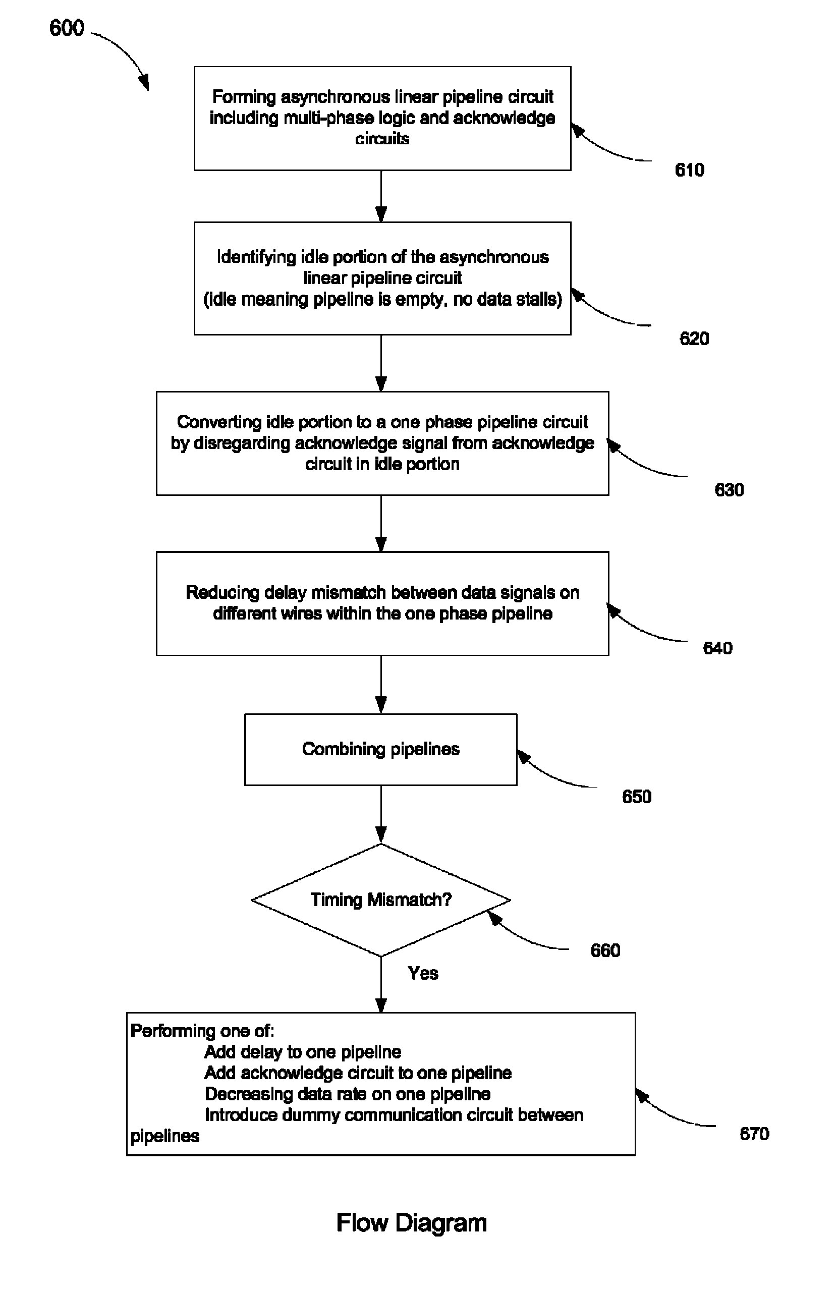
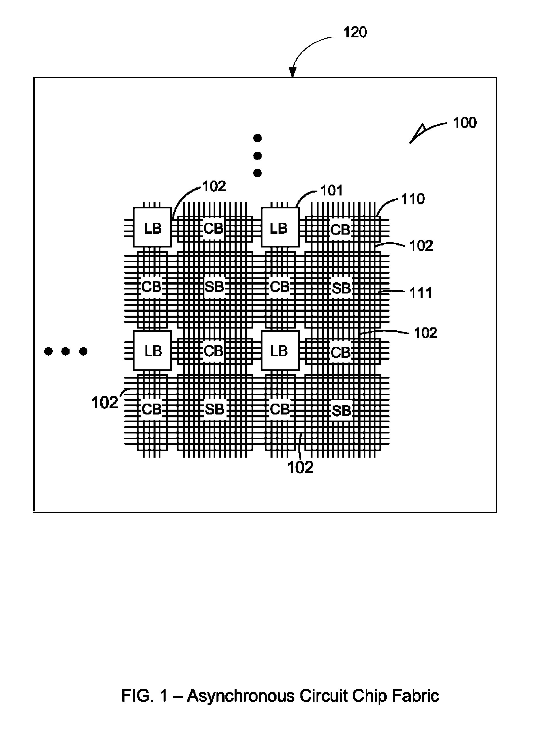
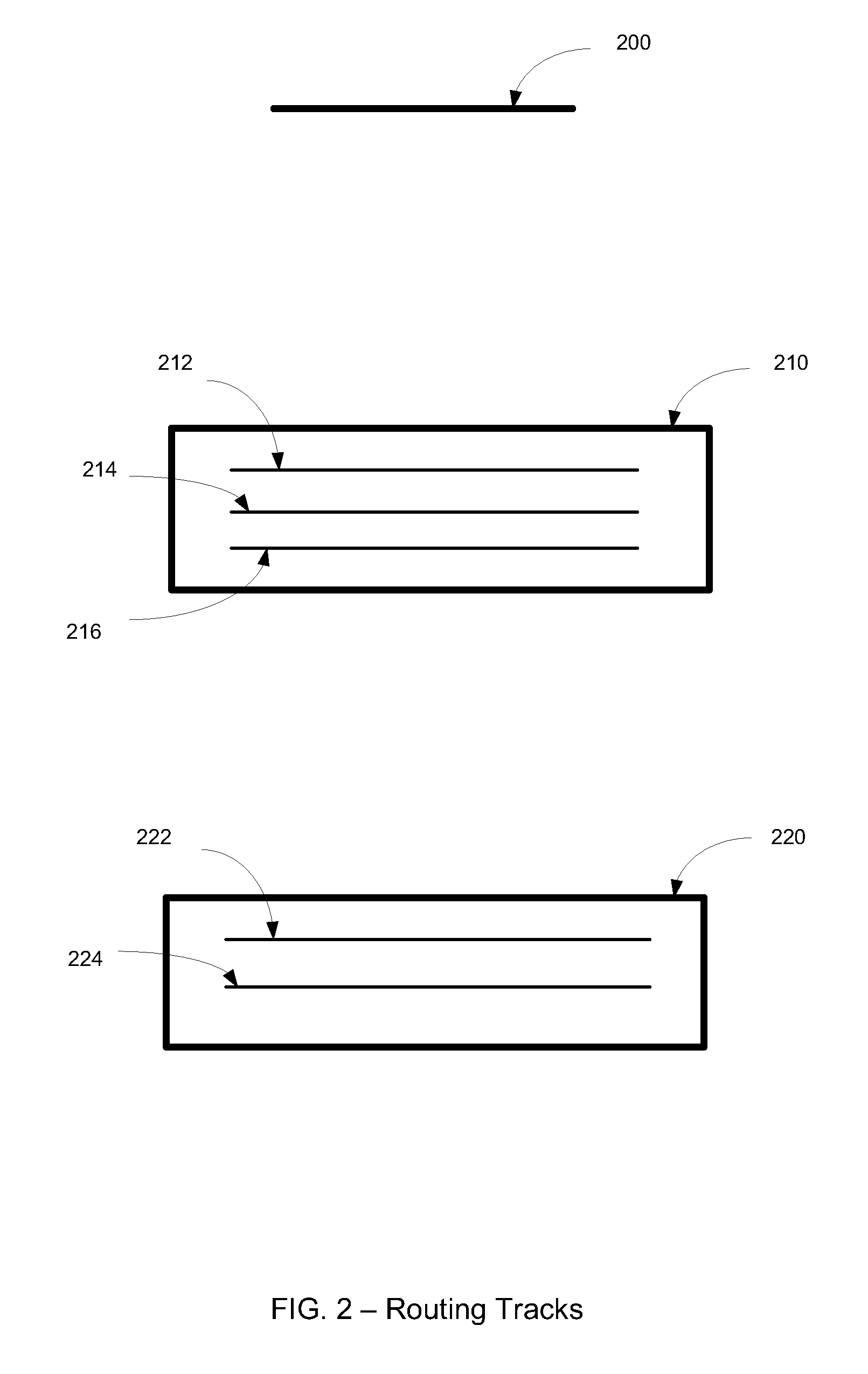
BACKGROUND[0001]Asynchronous digital systems, unlike their synchronous counterparts, often operate without centralized control or a global clock signal to coordinate operations. In some asynchronous systems, operations occur under distributed control, and concurrent modular hardware components with well-defined communication interfaces may communicate and synchronize functions over channels implemented using signaling or handshake protocols on sets of wires.BRIEF DESCRIPTION OF THE DRAWINGS[0002]Some embodiments of the disclosed technology are illustrated by way of example and not limitation in the figures of the accompanying drawings in which:[0003]FIG. 1 is a diagrammatic view of an example asynchronous circuit chip fabric according to various embodiments of the invention;[0004]FIG. 2 is a diagrammatic view of example routing tracks according to various embodiments of the invention;[0005]FIG. 3 illustrates a four-phase handshake protocol, according to various embodiments of the in...

Claims


Application Information

Patent Timeline
Patent Type & Authority Patents(United States)
IPC IPC(8): H03K19/177H01L25/00
CPCH03K19/0966
Inventor NIJSSEN, RAYMONDCHAUDHARY, KAMALMANOHAR, RAJITLAFRIEDA, CHRISTOPHERKELLY, CLINTON W.EKANAYAKE, VIRANTHA
Owner ACHRONIX SEMICON CORP
Why Eureka
Try Eureka