Mist generator and mist emission rendering apparatus

a technology of mist generator and mist, which is applied in the direction of fuel injection apparatus, non-fuel substance addition to fuel, combustion air/fuel air treatment, etc., can solve the problems of easy deformation of the mechanism, high mist particle diameter, and heat generation of the ultrasonic transducer itself, so as to achieve the effect of increasing the atomization efficiency, and reducing the size of the apparatus

Inactive Publication Date: 2011-05-03
TOMONO AKIRA
View PDF63 Cites 27 Cited by
  • Summary
  • Abstract
  • Description
  • Claims
  • Application Information

AI Technical Summary

Benefits of technology

[0103]As shown in, for example, FIG. 4, FIG. 5, FIG. 10, FIG. 17, FIG. 19, FIG. 20, FIG. 21, and FIG. 27, the ultrasonic waves emitted from the ultrasonic transducer (40) are converged by the ultrasonic convergence and reflection mechanism (25), and are strongly irradiated near the end (Foc) of the liquid for atomization (Liq2). In this case, the liquid is locally dispersed, and the ultrasonic waves are generally hemispherically scattered in a traveling direction at a position where the liquid is dispersed. When the scattered ultrasonic waves are converged into the ultrasonic reflection tube (27 or 29) again to be traveled in the axial direction of the tube, a part of droplet dispersed liquids with large particle diameter generated as by-products when the above-mentioned liquid is atomized, is also atomized, thus increasing atomization efficiency. As compared with the case where the above-mentioned ultrasonic convergence and reflection mechanism (25) and the above-mentioned ultrasonic reflection tube (27 or 29) are not used, the amounts of mist over two to three times are generated.
[0104]Moreover, since the liquid for atomization (Liq2) locally disperses and it is atomized as described above, it is suitable for the object of atomizing a small amount of liquid. Hence, using the liquid as the chemical-containing liquid (Wa) makes it possible to achieve the mist generator whose utilization efficiency of the chemical is very high. Additionally, it is easy to atomize various chemical-containing liquids while exchanging them.
[0105]By using the above-mentioned ultrasonic convergence and reflection mechanism (25) and the ultrasonic reflection tube (27 or 29) in combination, quite a lot of fine-particles generated within the reflection tube are flown in the axial direction of the tube by a pressure of the ultrasonic waves which travel in the axial direction of the tube. The air flow is generated in the tube, thus allowing the mist generated by the ultrasonic energy to be discharged to the outside.
[0106]In the experiment shown in FIG. 5, the longer the ultrasonic reflection tube (27) is, the higher the mist goes up, thus allowing the mist to be discharged to the height exceeding 100 cm from the liquid level. Meanwhile, using an inclined tube, a curved tube, or a long tube makes the ultrasonic reflection tube more effective in dropping the droplet liquid from the lower part of the tube. Namely, the ultrasonic reflection tube of the present invention has the mist / liquid separating function for carrying the mist toward the tip thereof only by the traveling waves, and dropping the droplet liquid. Hence, in embodiments of the present invention shown in FIG. 4, FIG. 5, FIG. 10, FIG. 17, FIG. 18, FIG. 19, FIG. 20, FIG. 21, and FIG. 27, the air flow generating means composed of a fan (wing) and a motor which have been conventionally indispensable can be eliminated. It has profound effects on down-sizing and economization.
[0107]Moreover, since a portion where the liquid is atomized is separated from the surroundings by providing the above-mentioned ultrasonic reflection tube (27 or 29); there is an effect of reducing sound generated during atomization. A calm mist generator can be achieved.
[0108]When the small liquid container (20) containing the liquid for atomization (Liq2) is used while floating it on the ultrasonic propagation medium (Liq1) as shown in FIG. 12 and FIG. 21, the ultrasonic propagation path (Dp) from the plane of vibration (40F) of the ultrasonic transducer to the liquid level of the liquid for atomization (Liq2) can be maintained at almost constant length regardless of the amount of Liq2. Thereby, the atomization is stabilized and a large amount of mist with fine-grain is generated. A mist generator with excellent atomization efficiency can be achieved.Effects According to Means 2

Problems solved by technology

In the case of the cantilevered suspension structure, however, since it is difficult to vibrate the vibration point at high frequency, particle diameters of the generated mists are apt to be large and uneven.
The mists with large particle diameters disperse around the circumference of the apparatus without evaporating, thus causing a problem leading to contaminations.
Additionally, there are problems that an amount of atomization per unit time is small since the contact portion is small, production thereof is difficult since a contact mechanism portion between the tip of the ultrasonic transducer and the liquid retaining portion requires high accuracy, and the mechanism portion is easily degraded.
In the disk type ultrasonic transducer driven at the high frequency, however, the ultrasonic waves reflect on the surface of the element once the liquid stops existing in the plane of vibration, causing a problem that the ultrasonic transducer itself generates heat to increase a temperature thereof.
There are similar problems also in the element utilizing the magnetostrictive effect.
In other words, since there is a risk that the ultrasonic transducer may be destroyed, the mist generator for atomizing a small amount of liquid by the ultrasonic waves with a high frequency has not been well studied so far in the field of household articles.
However, even when one type of aroma is discharged for a long time, people stops feeling the aroma shortly since they have smell adaptive characteristics, so that an expensive perfume becomes useless easily.
When a perfume that is strong in physiological influence is used, there may also arise a problem which is not preferable on healthy.
Moreover, since the conventional ultrasonic mist generator is hard to be cleaned because of its structure, remaining perfume tends to contaminate the inside of the apparatus when using a perfume-containing liquid.
It has hardly spread as a whole because of such a maintenance problem.
A first problem is related to means for atomizing the liquid.
For this reason, a rate for the ultrasonic energy to be used for atomization is small, thus causing less atomization efficiency.
Moreover, when the air flow generating means 79 is used in order to discharge the mist, a part of droplet dispersed liquids AK2-F will be carried together with the mist, causing a problem that the liquids are dispersed around the circumference from an opening 59 to contaminate it.
A second problem is related to means for changing an aroma type.
However, a volume of the liquid storage 21 is large, and it is necessary to create a situation where the perfume-containing liquid Wa above T2 always exists in order to prevent that the ultrasonic transducer 40 falls in a boil-dry state, and thus even when the liquid container 13 is exchanged to a liquid container containing another perfume, the liquids before and after the exchange are mixed with each other in the liquid storage 21, making it difficult to switch the aroma at high speed and clearly.
A third problem is related to cleaning and maintenance.
For this reason, it is troublesome to clean the inside of the apparatus and its maintainability is poor.
This is a serious problem as the home mist generator.
When the perfume-containing liquid Wa is left as it is, it will cause perfume degradation and bacteria breeding.
That is unsanitary and bad also for health rather than healing.
A fourth problem is related to the air flow generating means 79.
Stage effects are unsatisfactory.
As described above, the ultrasonic mist generator for home use has less atomization efficiency, and does not primarily have a structure aiming at switching the aroma, so that it might not be used as an aroma switching apparatus.
Even when it is used as a single-aroma generator, there are maintenance problems, such as useless consumption of the perfumes, troublesome cleaning, or the like.
Moreover, there are problems that the apparatus tends to be large-scale, and there is no function for increasing healing effects by producing the discharge of the mist.

Method used


Image

  • Mist generator and mist emission rendering apparatus
  • Mist generator and mist emission rendering apparatus
  • Mist generator and mist emission rendering apparatus

Examples


first embodiment

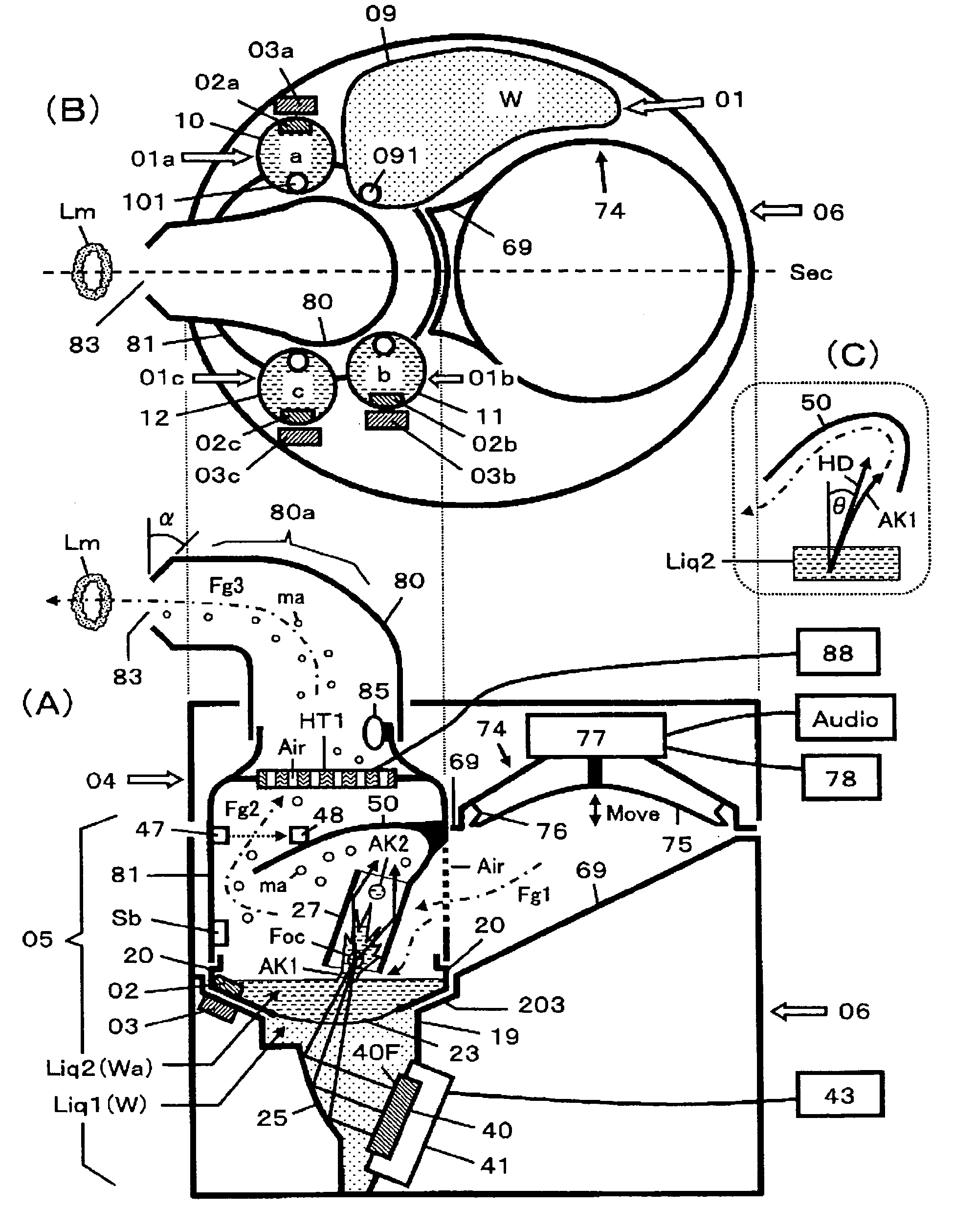
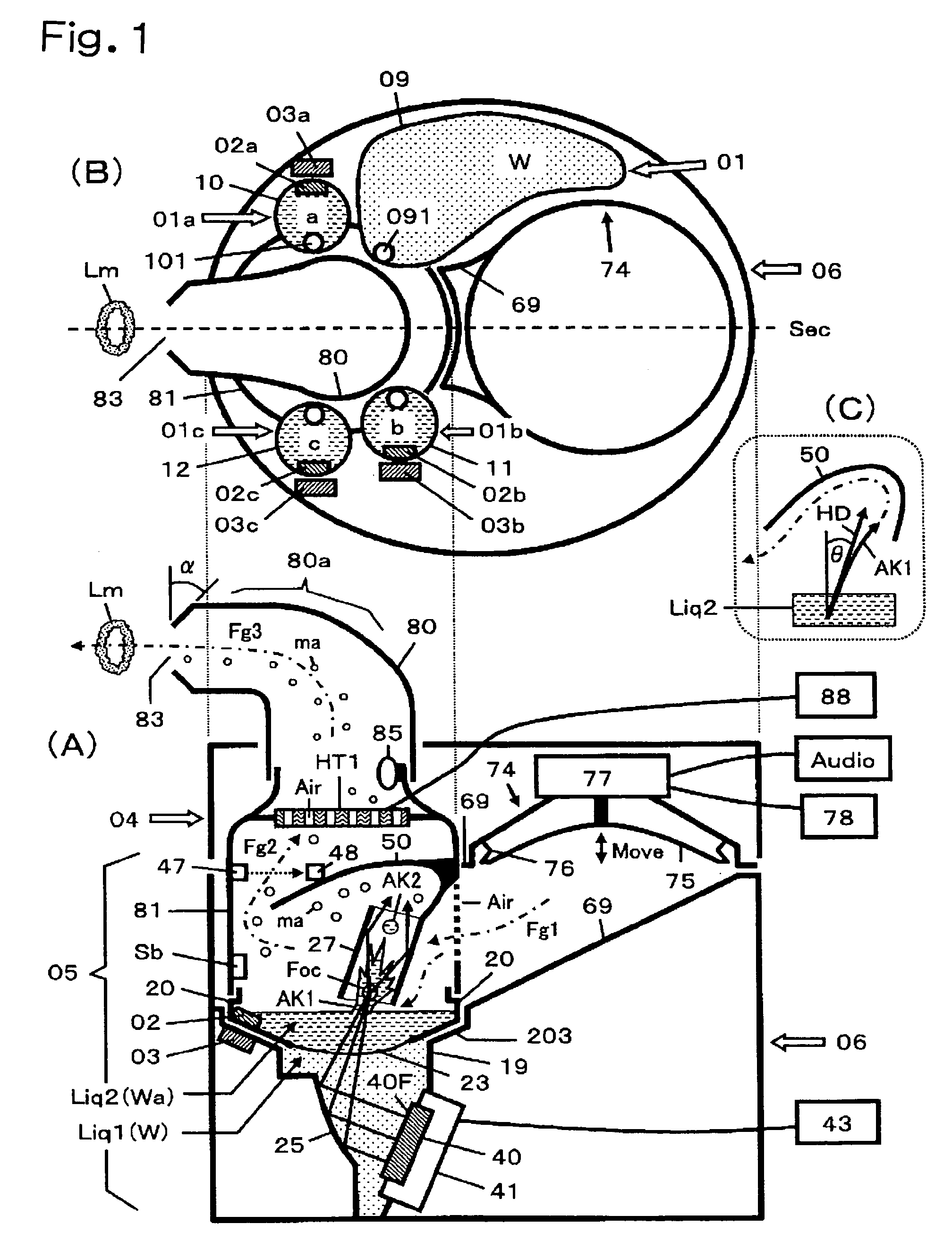
[0166]FIG. 1 is a first embodiment of the present invention, and shows a mist generator for discharging a mist or vapor which contains various chemicals to distant locations. FIG. 1(A) is a figure in which a longitudinal section of the apparatus is viewed from the side, and FIG. 1(B) is a top view in a state where an upper housing 04 is removed in FIG. 1(A). FIG. 1(A) shows the longitudinal section at dashed line Sec of FIG. 1(B). FIG. 2 is an exploded view showing a component constitution of the embodiment. Additionally, FIG. 3 is a view for describing in detail a portion which atomizes a liquid in FIG. 1.

[0167]In FIG. 1(A), reference numeral 05 represents means for atomizing the liquid, reference numeral 06 represents the lower housing, symbol HT1 represents heating means, reference numeral 80 represents a mist discharge tube, and reference numeral 74 represents means for instantaneously generating an air current (air gun).

[0168]First, a constitution of the means 05 for atomizing ...

second embodiment

[0266]FIG. 5 is a second embodiment of the present invention, and shows a sectional view of the mist generator effectively using the ultrasonic convergence and reflection mechanism 25, the ultrasonic reflection tubes with long axis 27, 271, and 272. Description will be made focusing on different points as compared with FIG. 1. Note herein that GD1 to GD4 correspond to claim 1, and GD5 corresponds to claim 1 to claim 4.

[0267]In FIG. 5 (GD1), the ultrasonic transducer 40 is provided in the liquid container 19 while placing a plane of vibration thereof sideways. The liquid for atomization Liq2 (Wa) is poured into the liquid container 19 from the nozzle of the liquid container 10 which stores the chemical-containing liquid Wa so that the liquid level is kept constant. Liq2 fills the plane of vibration.

[0268]The ultrasonic concave mirror lens 25 which is the ultrasonic convergence and reflection mechanism is provided on the left-hand side of the ultrasonic transducer 40 so as to be adjac...

third embodiment

[0295]FIG. 8 is a third embodiment of the present invention, and shows a mist generator for atomizing the liquid which contains various chemicals (perfumes), and mixing the mist or vapor to be discharged. FIG. 8(A) is a figure in which a longitudinal section of the apparatus is viewed from the side, and FIG. 8(B) is a figure in which a mixer KS of the mist or vapor in which the ultrasonic reflection tubes 29, 29b and the air tube 81 are integrated in FIG. 8(A) is viewed from the top. The mixer KS can be integrally molded by plastics or the like. FIG. 9 is a view showing a component constitution in the embodiment.

[0296]Six means similar to the liquid atomization means 05 shown in FIG. 1 are circumferentially provided at the lower housing 06 in FIG. 8. Two of them are shown at right and left in FIG. 8(A). In the same figure, reference numerals 10 and 11 are the liquid containers for storing the perfume-containing liquids Wa and Wb in which the perfumes a and b are contained in that wa...


PUM

PropertyMeasurementUnit
lengthaaaaaaaaaa
frequencyaaaaaaaaaa
temperatureaaaaaaaaaa

Abstract

An apparatus includes an ultrasonic transducer; an ultrasonic propagation medium disposed so as to fill a plane of vibration of the transducer; liquid retaining means disposed so as to be in contact with an end face of the medium; and an ultrasonic focusing reflecting mechanism disposed in an ultrasonic propagation path, thereby the apparatus attains discharging into air and atomization of the liquid by use of ultrasonic waves. Atomization efficiency is enhanced by the use of an ultrasonic reflection tube, and mist emission is carried out. Use is made of a compact liquid container equipped at its bottom with an ultrasonic transmission membrane. Various types of liquids can be atomized by changing the direction of ultrasonic course.

Description

TECHNICAL FIELD[0001]The present invention relates to a mist generator for discharging a mist containing chemicals which are used in lives, such as perfumes, medicines, fungicides, and deodorizers, using ultrasonic waves, and a mist discharge producing apparatus using the mist generator. Note that, in the present invention, the mist generator shall include apparatuses for atomizing or evaporating a liquid, and apparatuses for discharging the mist.BACKGROUND ART[0002]Prior arts and problems thereof will be described concerning an apparatus for discharging a mist which contains a perfume as an example of the above-mentioned chemicals.[0003]In recent years when people are subjected to various stress, fragrance generators using an ultrasonic mist generator attract attention as products for giving people healing. They will become attractive products if various aromas c˜n be presented while switching them.[0004]Generally, while an element with a piezo-electric effect or a magnetostrictive...

Claims


Application Information

Patent Timeline
Patent Type & Authority Patents(United States)
IPC IPC(8): B01F3/04
CPCA01M1/205B05B7/0012A61M11/005A61M11/041A61M21/02B05B17/0615F24F6/12A61M11/042A61M11/045A61M16/164A61L9/145A61M2021/0016A61M2021/0027A61M2021/0044A61M2205/331A61M2205/3368A61M2205/3375A61M2205/3382A61M2205/3386A61M2205/3389A61M2205/3569A61M2205/3592A61M2205/3653A61M2205/502A61M2205/52A61M2205/60A61M2205/6018B05B12/081F24F2006/125Y10S261/65Y10S261/48Y02B30/80A61M11/001A61M11/048B05B1/002Y02B30/70A61M2205/3379
Inventor TOMONO, AKIRAUEHARA, AKIO
Owner TOMONO AKIRA
Why Eureka
Try Eureka