Synchronous rectifier control using load condition determination

a technology of load condition determination and synchronous rectifier, which is applied in the direction of electric variable regulation, process and machine control, instruments, etc., can solve the problems of capacitance exceeding the conduction loss of the corresponding diode, power dissipation during the forward current of the diode, and switching losses

Active Publication Date: 2011-05-03
INFINEON TECH AUSTRIA AG
View PDF6 Cites 26 Cited by
  • Summary
  • Abstract
  • Description
  • Claims
  • Application Information

AI Technical Summary

Problems solved by technology

These diodes, however, dissipate power during the diodes' forward current conduction.
Under light loads, especially at high switching frequencies, switching losses due to the charging and discharging of MOSFET device capacitance may actually exceed conduction losses in corresponding diodes.
One of the challenges of designing such a system is detecting a load condition and making the determination of whether to activate or deactivate the SR MOSFET switches in the power converter circuit.
The duty ratio of the primary switch, however, does not always indicate the load level of the power supply directly.
In this case the duty ratio of the primary switch is much shorter than normal conditions, but shutting off the SR MOSFET devices under low duty cycle conditions in this case would not be power efficient because of high currents running though the switching devices.
The primary disadvantage of using the primary switch turn on duty ratio is that more accurate information about the load level is available from signals present on the secondary side of the power converter.
This solution, however, is disadvantageous because of losses in the shut resistor and the difficulty of measuring current at different load levels.

Method used


Image

  • Synchronous rectifier control using load condition determination
  • Synchronous rectifier control using load condition determination
  • Synchronous rectifier control using load condition determination

Examples


Embodiment Construction

[0023]The making and using of the presently preferred embodiments are discussed in detail below. It should be appreciated, however, that the present invention provides many applicable inventive concepts that can be embodied in a wide variety of specific contexts. The specific embodiments discussed are merely illustrative of specific ways to make and use the invention, and do not limit the scope of the invention.

[0024]The present invention will be described with respect to preferred embodiments in a specific context, namely a switched-mode power converter. The invention may also be applied, however, to other circuits where SR MOSFETs or other switching devices are used.

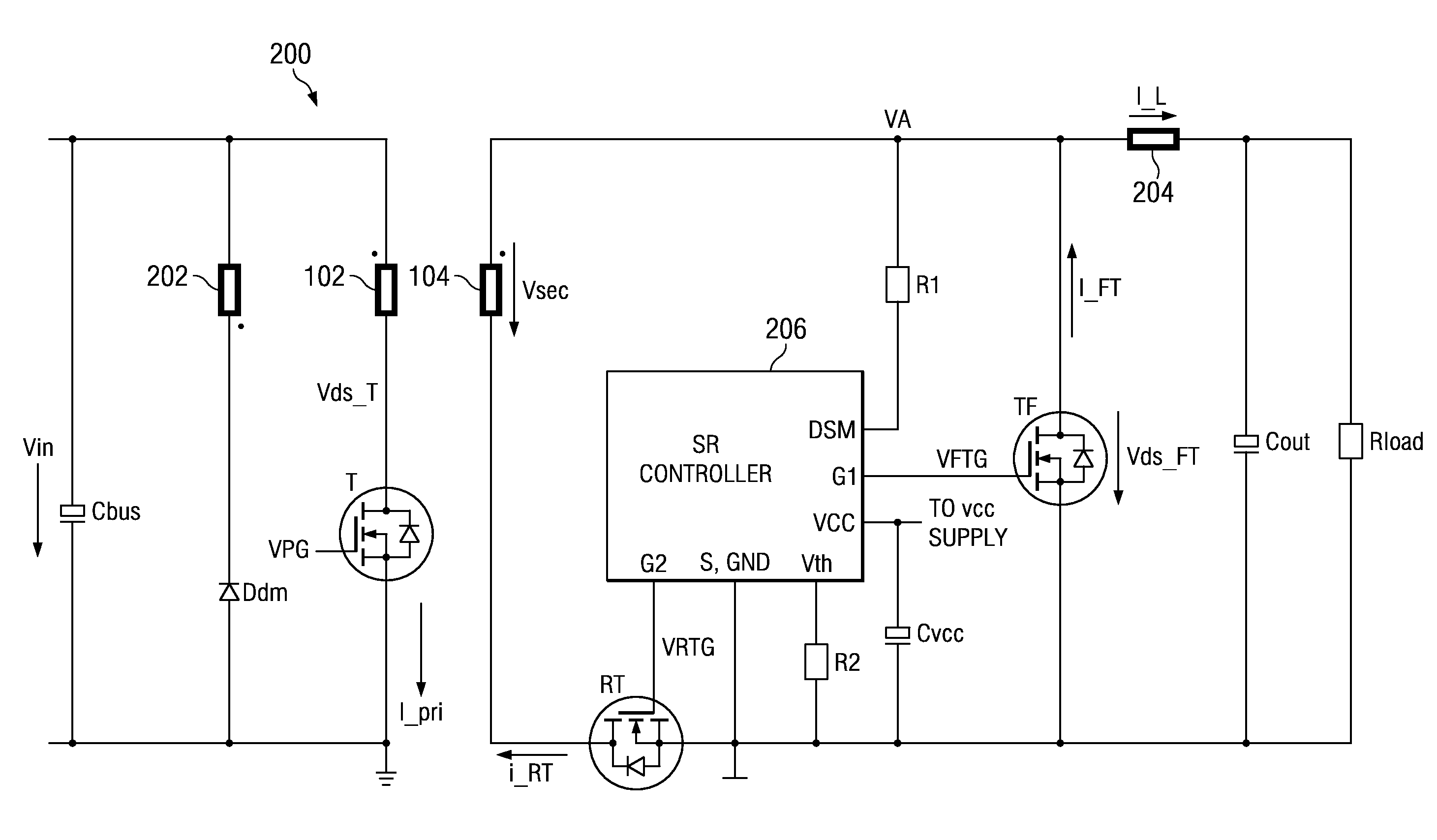
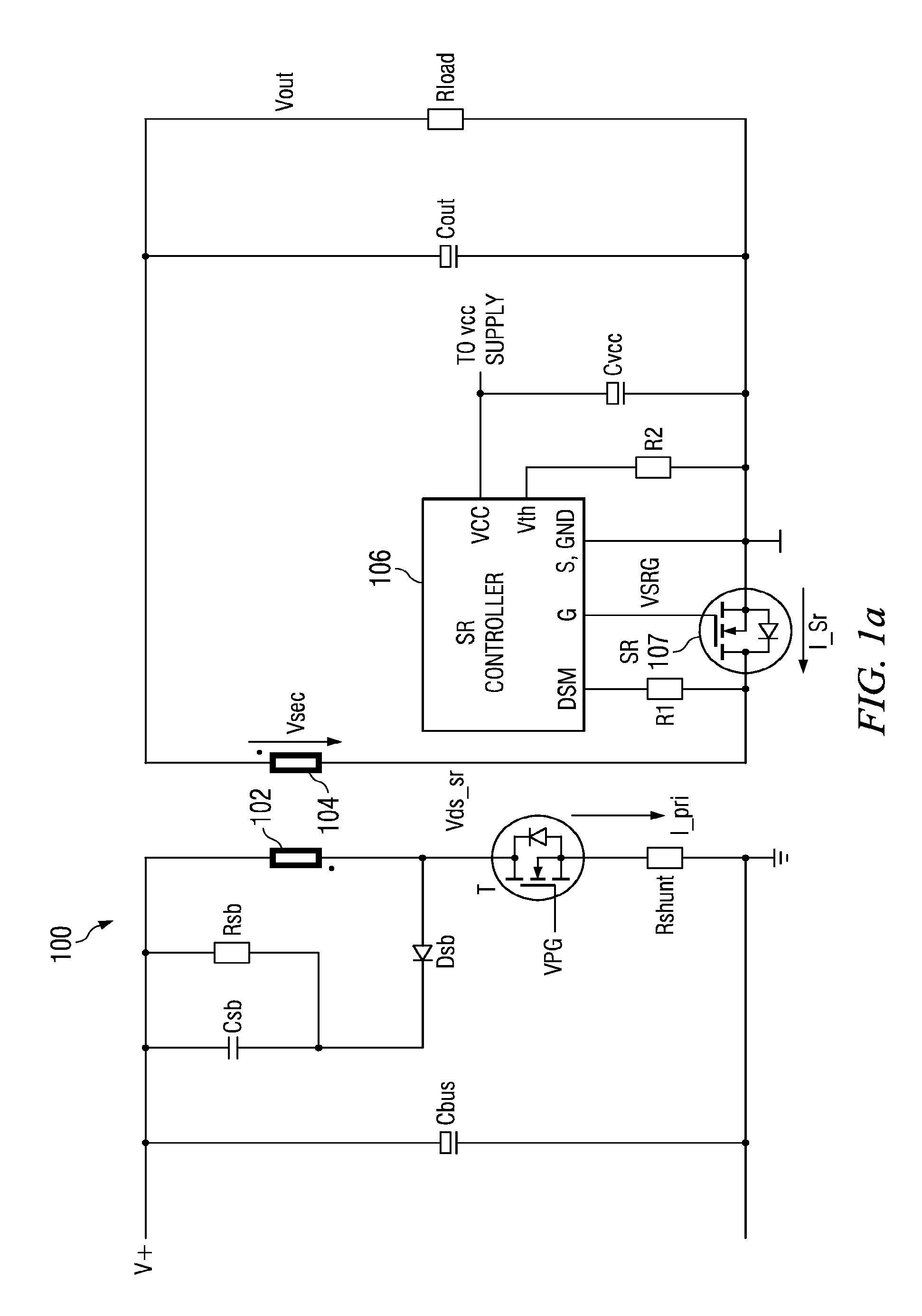
[0025]FIG. 1 shows an exemplary power converter circuit in a flyback configuration incorporating the features of embodiments of the present invention. In FIG. 1, a transformer of primary side coil 102 and secondary side coil 104 is depicted. A primary control circuit pulse width modulator (not shown) drives gate voltag...


PUM


Abstract

In accordance with an embodiment of the present invention, a method of operating a switched power supply is disclosed. The method comprises determining a current load on a secondary side of a transformer by measuring a ratio between a secondary side current conduction time and a primary switching period of the power supply and comparing the current load with a predetermined threshold. A synchronous rectification (SR) MOSFET coupled to the secondary side of the transformer is disabled if the current load is less than the preset threshold.

Description

TECHNICAL FIELD[0001]The present invention relates generally to a circuit and method to improve the operation of a switched-mode power supply converter, and more particularly, to a circuit and method for efficient operation of a DC-DC converter circuit using a synchronous rectifier (SR).BACKGROUND[0002]Switched mode power supplies are efficient power supplies that achieve their power efficiency by minimizing dissipative voltage drops with the power supply circuit. Traditional switched mode power supply systems typically use diodes to control and direct and the conduction of current throughout the switched mode power supply. These diodes, however, dissipate power during the diodes' forward current conduction. One technique used to prevent power losses from the forward conduction of diodes is to use synchronous rectifier (SR) MOSFETs. Rather than dissipate power across a diode drop of about 700 mV, an SR MOSFET based power supply system can be designed to have a lower voltage drop, fo...

Claims


Application Information

Patent Timeline
Patent Type & Authority Patents(United States)
IPC IPC(8): H02M3/335
CPCH02M3/33592Y02B70/1475Y02B70/10
Inventor HU, JING
Owner INFINEON TECH AUSTRIA AG
Why Eureka
Try Eureka