Method of direct hot tapping into a multiple production string without removing outer layers of casing

a production string and hot tapping technology, applied in the field of hot tapping systems, can solve the problems of casing falling in collapse, and achieve the effect of better controlling tensile/clamping loads

Inactive Publication Date: 2011-05-10
BLOWOUT TOOLS
View PDF4 Cites 11 Cited by
  • Summary
  • Abstract
  • Description
  • Claims
  • Application Information

AI Technical Summary

Benefits of technology

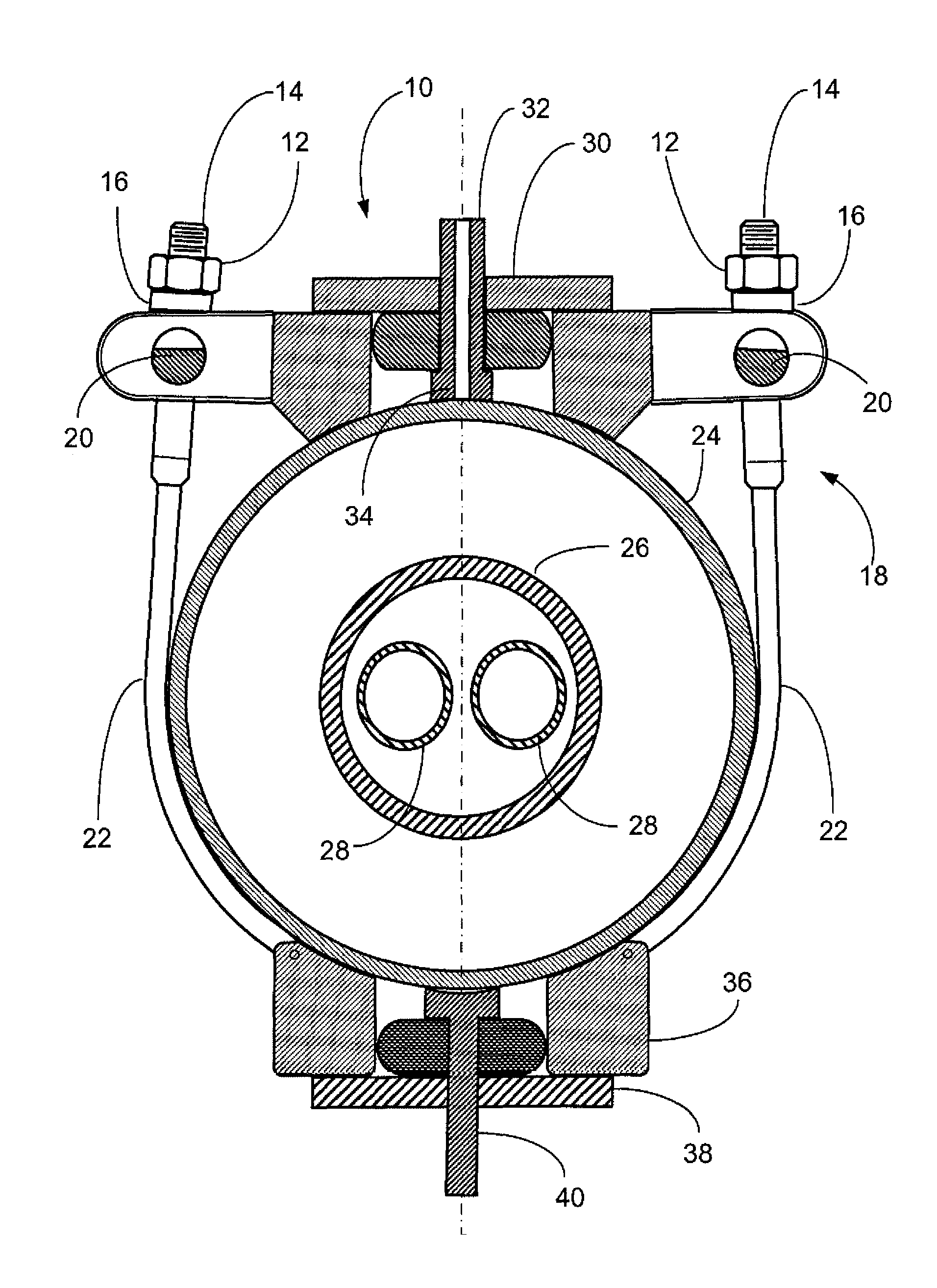
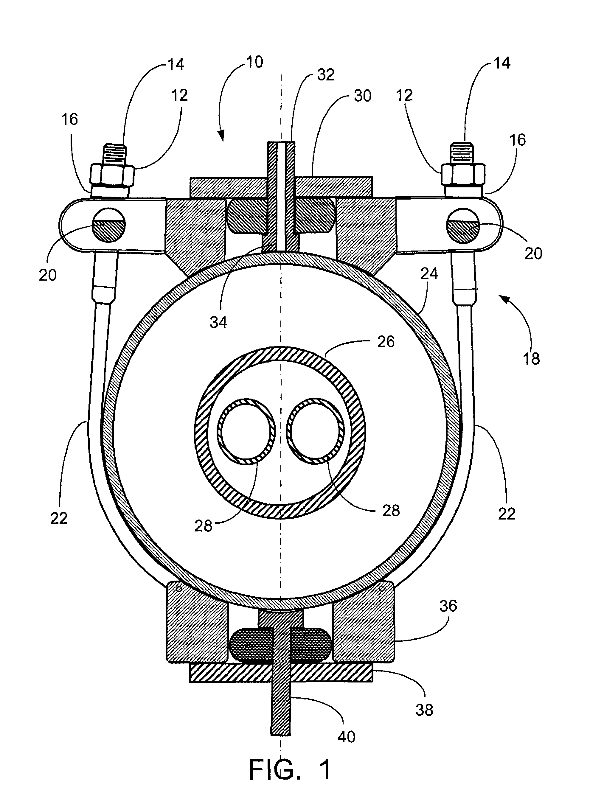
[0010]The multiple string hot tap system is a hot tapping system that eliminates the need to remove the outer layers of casing to obtain access to the production tubing. The system is designed around a unique hot tap clamping system which has a 4 or 6 inch diameter bore in the center of the clamps. This bore in the center of the clamps will be used to drill an access hole in the outer casing after the casing has been hot tapped. The access holes are later used to hot tap the next casing string.
[0011]The multiple string hot tap system eliminates the need for removal of the outer layers of casing to gain access to the inner layers of casing and the production tubing. The system designed around two clamps (a front clamp and a rear clamp). The two clamps are connected together with four chains. The chains are tensioned by applying torque to the nuts on the chain connector. The tension on the chains is based on the outer casing or surface casing size, wall thickness and material properties. If the chains are tensioned too high, the casing will fall in collapse. The maximum hot tapping pressure for the assembly is controlled by the outer casing specification and the specific set up of the multiple string hot tap assembly. The maximum hot tapping pressure can be increased by adding tension chains and increasing clamp bearing area.

Problems solved by technology

If the chains are tensioned too high, the casing will fall in collapse.

Method used


Image

  • Method of direct hot tapping into a multiple production string without removing outer layers of casing
  • Method of direct hot tapping into a multiple production string without removing outer layers of casing
  • Method of direct hot tapping into a multiple production string without removing outer layers of casing

Examples


Embodiment Construction

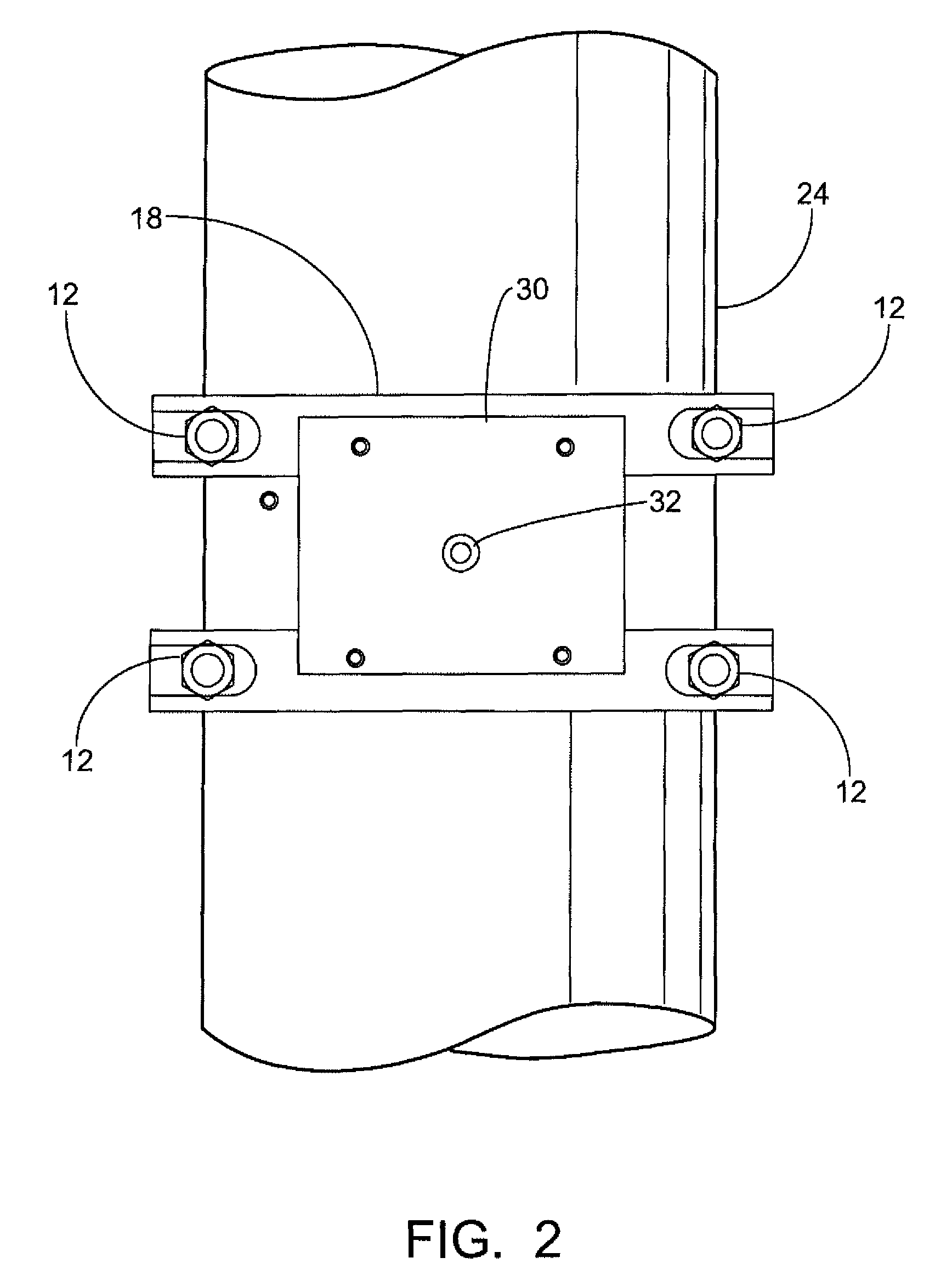
[0026]As will be seen more clearly in FIGS. 1 through 13, the method of the present invention relates to hot tapping a damaged oil well to release any pressure within the layers of casing or pipe, without removing the outer casing string to access inner casing strings and production tubing. The novel method utilizes a multiple string hot tap system 10, also referred to as the novel System 10. The equipment is designed to allow hot tapping of each string of pipe in the completion without removal of the support clamps.

[0027]In the present system, as illustrated in the various FIGS. 1 through 13, a front clamp 18 and a rear clamp 36 are connected together with four tension chains 22. The chains 22 are tensioned by applying torque to the nuts 10 on the chain connectors 14. The tension on the chains 22 is based on the outer casing size, wall thickness, and material properties. If the chains 22 are tensioned too high, the casing 24 will fall and collapse. This amount of tension in the cha...


PUM


Abstract

A method of hot tapping into a multiple string configuration for obtaining access to the production tubing without removing outer layers of casing by providing a multiple casing string that includes at least an outer casing and an inner casing or production string; mounting a clamp assembly around the wall of the outer casing; hot tapping a small opening through the outer casing wall to capture any pressurized fluid through the opening; cutting first and second large openings through the wall of the outer casing to access the inner casing, each opening being approximately 180 degrees from the other opening; through the first opening, drilling a small hole through the wall of the inner casing to capture any pressurized fluid through the opening in the inner casing; and inserting an anvil through the second opening to contact and stabilize the wall of the inner casing to prevent the casing from moving while the casing is drilled.

Description

CROSS-REFERENCE TO RELATED APPLICATIONS[0001]Priority of U.S. Provisional Patent Application Ser. No. 60 / 990,498, filed Nov. 27, 2007, incorporated herein by reference, is hereby claimed.STATEMENT REGARDING FEDERALLY SPONSORED RESEARCH OR DEVELOPMENT[0002]Not applicableREFERENCE TO A “MICROFICHE APPENDIX”[0003]Not applicableBACKGROUND OF THE INVENTION[0004]1. Field of the Invention[0005]The process of the present invention relates to gaining access to the production tubing to vent fluid pressure within the tubing. More particularly, the present invention relates to a hot tapping system to vent pressurized fluids that eliminates the need to remove the outer layer of casing to obtain access to the production tubing.[0006]2. General Background of the Invention[0007]The conventional hot tap system is designed to allow hot tapping of the outer casing. For the conventional hot tap system, the outer casing must be removed by a process known as wedding caking to proceed to the next casing s...

Claims


Application Information

Patent Timeline
Patent Type & Authority Patents(United States)
IPC IPC(8): F16L55/07F16L41/06
CPCE21B29/00F16L41/06F16L41/065Y10T137/612Y10T137/6123Y10T137/0463Y10T137/0469
Inventor CENAC, MARTINROBICHAUX, RICHARD J.ANGERS, JR., JOHN WILLIAM
Owner BLOWOUT TOOLS
Why Eureka
Try Eureka