Dynamic tagging of network data based on service level objectives

a network data and service level technology, applied in the field of computer systems, can solve the problems of ineffective use of static techniques, communication gaps, and inability to effectively utilize static techniques, and achieve the effect of shortening response times

Active Publication Date: 2011-05-10
SYMANTEC OPERATING CORP
View PDF8 Cites 87 Cited by
  • Summary
  • Abstract
  • Description
  • Claims
  • Application Information

AI Technical Summary

Benefits of technology

[0007]Various embodiments of systems and methods for dynamic tagging of network data based on service level objectives are disclosed. According to one embodiment, a system comprises one or more processors and memory coupled to the processors. The memory comprises program instructions executable by the processors to identify a service level objective associated with a task that comprises a transmission of data packets over a network on behalf of an application, where the network includes one or more devices (such as routers, switches, etc.) configured to provide different levels of service to data packets based at least in part on service level indicators included within the packets. The instructions are executable to dynamically generate service level indicators corresponding to the identified service level objectives for inclusion in the data packets of the task, and to transmit the packets including the service level indicators into the network. On receiving a tagged packet, a network de

Problems solved by technology

In many cases, for example, enterprise application providers may rent connectivity across wide area networks from telecommunication carriers, but the enterprise application providers may have no control over the underlying network infrastructure managed by the carriers.
Applications that are intended to support different levels of services for different tasks or jobs—e.g., to provide a higher quality of service to an online order for goods worth a million dollars than to an order for goods worth ten dollars—may not be abl

Method used


Image

  • Dynamic tagging of network data based on service level objectives
  • Dynamic tagging of network data based on service level objectives
  • Dynamic tagging of network data based on service level objectives

Examples


Embodiment Construction

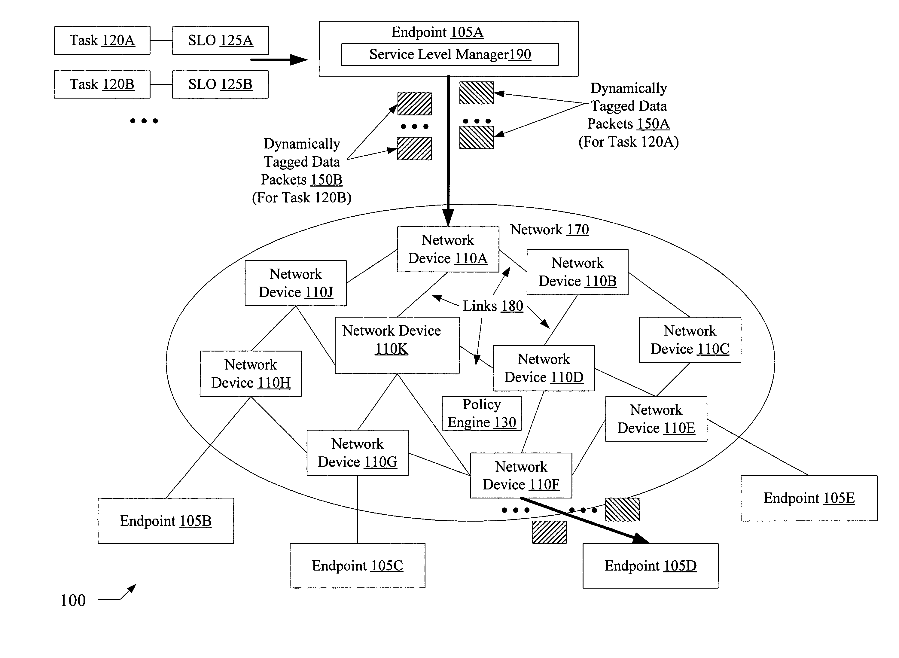
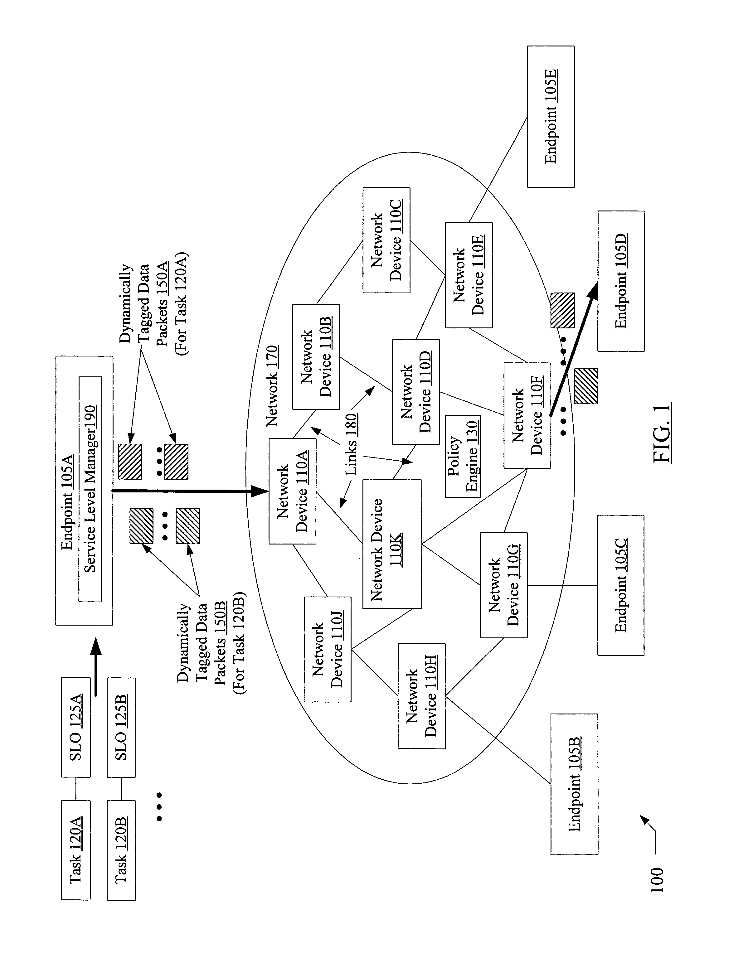
[0017]FIG. 1 is a block diagram illustrating a system 100 according to one embodiment. As shown, system 100 includes a network 170 linking a plurality of network devices 110 (e.g., devices 110A-110K) and a plurality of endpoints 105 (e.g., endpoint 105A-105E). Each network device 110 and each endpoint 105 is connected to at least one other network device or endpoint via one or more links 180 (which may include physical links, wireless links, or both physical and wireless links in various embodiments). The network 170 may also include one or more policy engines 130 (which may also be referred to herein as policy managers 130) configured to coordinate traffic flow in accordance with a set of rules or policies, as described below in further detail. The endpoints 105 may include, for example, various computing devices such as servers, workstations, personal computers, personal digital assistants, etc., each of which may be configured to execute various applications on behalf of clients....


PUM


Abstract

A system for dynamic tagging of network data based on service level objectives comprises one or more processors and memory coupled to the processors. The memory comprises program instructions executable by the processors to identify a service level objective associated with a particular task that comprises a transmission of data packets over a network on behalf of an application, where the network includes one or more devices (such as routers, switches, etc.) configured to provide different levels of service to data packets based at least in part on service level indicators included within the packets. The instructions are executable to dynamically generate service level indicators corresponding to the identified service level objectives for inclusion in the data packets of the task, and to transmit the packets including the service level indicators into the network.

Description

BACKGROUND OF THE INVENTION[0001]1. Field of the Invention[0002]This invention relates to computer systems and, more particularly, to tagging of network data packets in computer systems based on service level objectives.[0003]2. Description of the Related Art[0004]In today's highly interconnected computing environment, hardware and software from a variety of different vendors may be used in order to process service requests submitted by enterprise application clients. For example, when a user of a web-enabled stock trading application issues a request to buy shares using a web browser running on a personal computer (PC), the web browser and the operating system at the user's PC may be provided by a first vendor, the web application interface to the stock trading application may have been developed by another vendor, the PC hardware components (which may have been manufactured by a variety of vendors) may have been assembled by a different vendor, and so on. Various networking device...

Claims


Application Information

Patent Timeline
IPC IPC(8): H04L12/56
CPCH04L41/50H04L41/5003H04L47/2475H04L47/2433H04L47/10
Inventor DUFFY, STEPHENVAN RIETSCHOTE, HANS F.KRITOV, SLAVA
Owner SYMANTEC OPERATING CORP
Why Eureka
Try Eureka