Method for engineering connections in a dynamically reconfigurable photonic switched network

a dynamic reconfiguration and photonic switching technology, applied in the field of telecommunication networks, can solve the problems of inability to apply traditional span and path equalization methods in the context of dynamic reconfiguration of connections, significant physical design challenges in connection set-up and control, and achieve significant up-front and lifecycle network cost savings, the effect of improving the accuracy of network operation control

Inactive Publication Date: 2011-05-10
PROVENANCE ASSET GRP LLC +1
View PDF20 Cites 10 Cited by
  • Summary
  • Abstract
  • Description
  • Claims
  • Application Information

AI Technical Summary

Benefits of technology

[0023]By moving away from the traditional worst case based engineering rules the overall network design and cost can be significantly optimized. Advantageously, the invention provides end-to-end path performance optimization based on current network connectivity information and current physical performance parameters of the path, which leads to significant up-front and lifecycle network cost savings.
[0024]Use of current network connectivity information and current physical performance parameters of the path also confers better accuracy of network operations control.
[0025]Furthermore, the path engineering method according to the invention provides for flexibility of control. Thus, in one embodiment, a path switch or a path configuration change is prompted based on re...

Problems solved by technology

By removing OEO conversion for the passthru channels at the switching nodes, connection set-up and control become significant physical design challenges.
Furthermore, traditional section-by-section equalization cannot be performed; connections sharing a given fiber section now have su...

Method used


Image

  • Method for engineering connections in a dynamically reconfigurable photonic switched network
  • Method for engineering connections in a dynamically reconfigurable photonic switched network
  • Method for engineering connections in a dynamically reconfigurable photonic switched network

Examples


Embodiment Construction

[0039]The term ‘connection’ refers here to an end-to-end logical path, which can be set-up along a plurality of physical paths, using regenerators at intermediate nodes as / if needed, and employing one or more wavelengths.

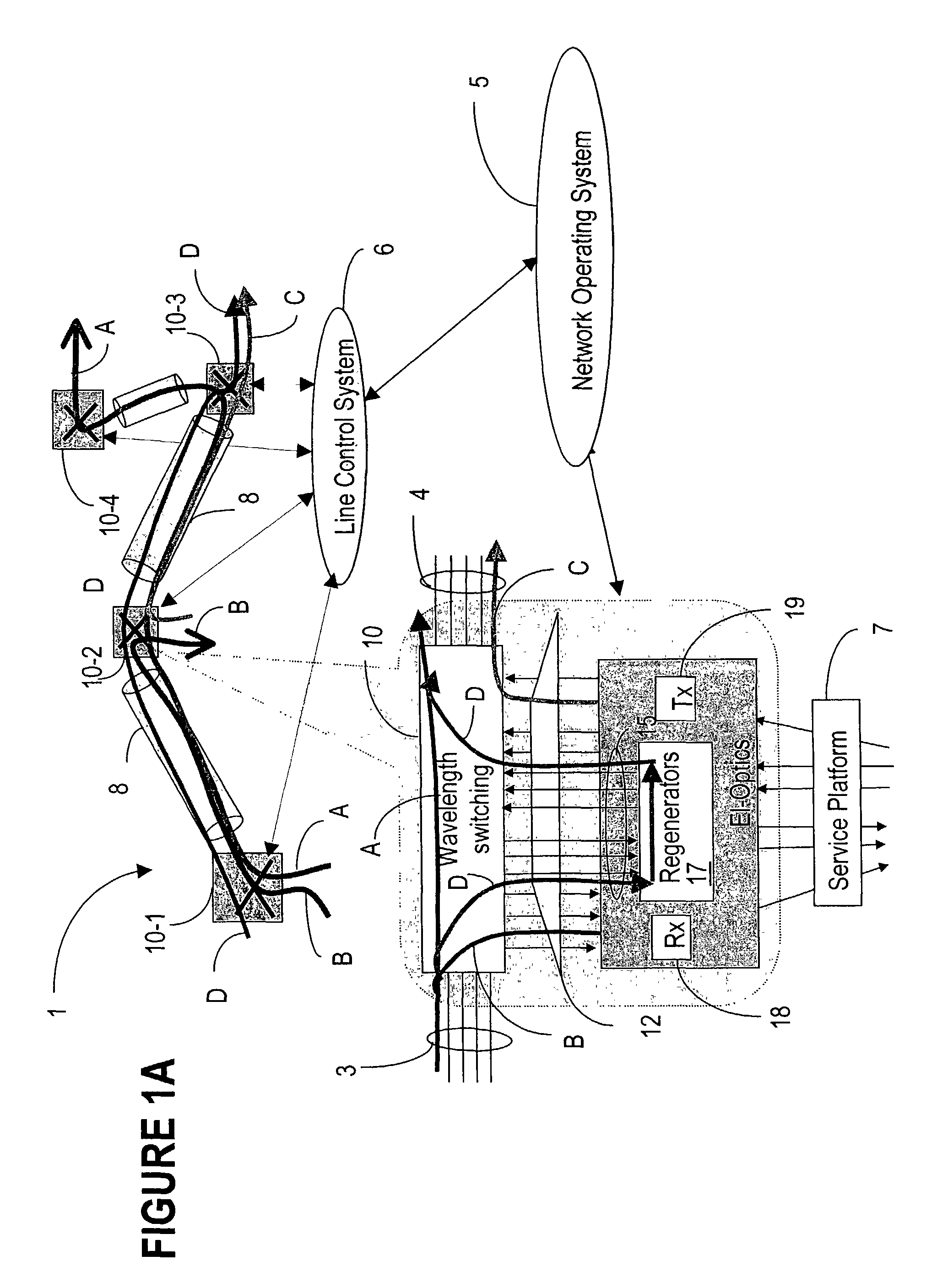
[0040]The term ‘flexibility site’ or ‘flexibility point’ refers to a node of a D / WDM network where connections could be added, dropped and / or switched from an input fiber to an output fiber. Such nodes are provided in the network according to the above-identified patent applications with a wavelength cross-connect or with an optical add / drop multiplexer.

[0041]The term ‘path’ refers here to a source-destination physical route (also referred to as an ‘A-Z path’ or A-Z connection). A path can have one or more configurations, due to the flexible regenerator placement and wavelength assignment capabilities. The term ‘link’ is used for the portion of the network between two flexibility sites, and the term ‘section’ refers to the portion of the network between two optical ...


PUM


Abstract

A method for engineering of a connection in a WDM photonic network with a plurality of flexibility sites connected by links comprises calculating a physical end-to-end route between a source node and a destination node and setting-up a communication path along this end-to-end route. An operational parameter of the communication path is continuously tested and compared with a test threshold. The path is declared established whenever the operational parameter is above the margin tolerance. The established path is continuously monitored by comparing the operational parameter with a maintenance threshold. A regenerator is switched into the path whenever the operational parameter is under the respective threshold, or another path is assigned to the respective connection. An adaptive channel power turn-on procedure provides for increasing gradually the power level of the transmitters in the path while measuring an error quantifier at the destination receiver until a preset error quantifier value is reached. As the connection ages, the power is increased so as to maintain the error quantifier at, or under the preset value. The path operation is controlled using a plurality of optical power/gain control loops, each for monitoring and controlling a group of optical devices, according to a set of loop rules.

Description

PRIORITY PATENT APPLICATION[0001]Provisional US Patent Application “Method for Engineering Connections in a Dynamically Reconfigurable Photonic Switched Network” (Zhou et al.) Ser. No. 60 / 306,302 filed Jul. 18, 2001.FIELD OF THE INVENTION[0002]The invention is directed to a telecommunication network, and in particular to a method for engineering connections in a dynamically reconfigurable photonic network.BACKGROUND OF THE INVENTION[0003]Current transport networks are based on a WDM (wavelength division multiplexing) physical layer, using point-to-point (pt-pt) connectivity. A WDM optical signal comprises a plurality of transmission channels, each channel carrying an information (data) signal modulated over a carrier wavelength.[0004]The span reach, or the distance between a transmitter and the next receiver, is limited by the combined effect of attenuation and distortion experienced by the signal along the optical fiber. A solution to increase the span reach is to place optical amp...

Claims


Application Information

Patent Timeline
IPC IPC(8): H04B10/04H04J14/02H04Q11/00
CPCH04Q11/0062H04J14/0241H04J14/0257H04J14/0267H04J14/0269H04J14/0227H04J14/0284H04Q2011/0083
Inventor ZHOU, JINGYUSOLHEIM, ALAN GLENAU-YANG, ROBERTWIGHT, MARK STEPHENSCHEERER, CHRISTIAN
Owner PROVENANCE ASSET GRP LLC
Why Eureka
Try Eureka