
Apparatus for improving detection efficiency of multiphoton microscopy systems by focus compensation, pupil image division, and parallel pupil rearrangement

a multi-photon microscopy and focus compensation technology, applied in the field of multi-photon microscopy, can solve the problems of fundamental loss of signal, inescapable geometric difficulty, waste of significant portion of signal,

Active Publication Date: 2011-05-17
PRAIRIE TECH
View PDF7 Cites 4 Cited by
  • Summary
  • Abstract
  • Description
  • Claims
  • Application Information

AI Technical Summary

Problems solved by technology

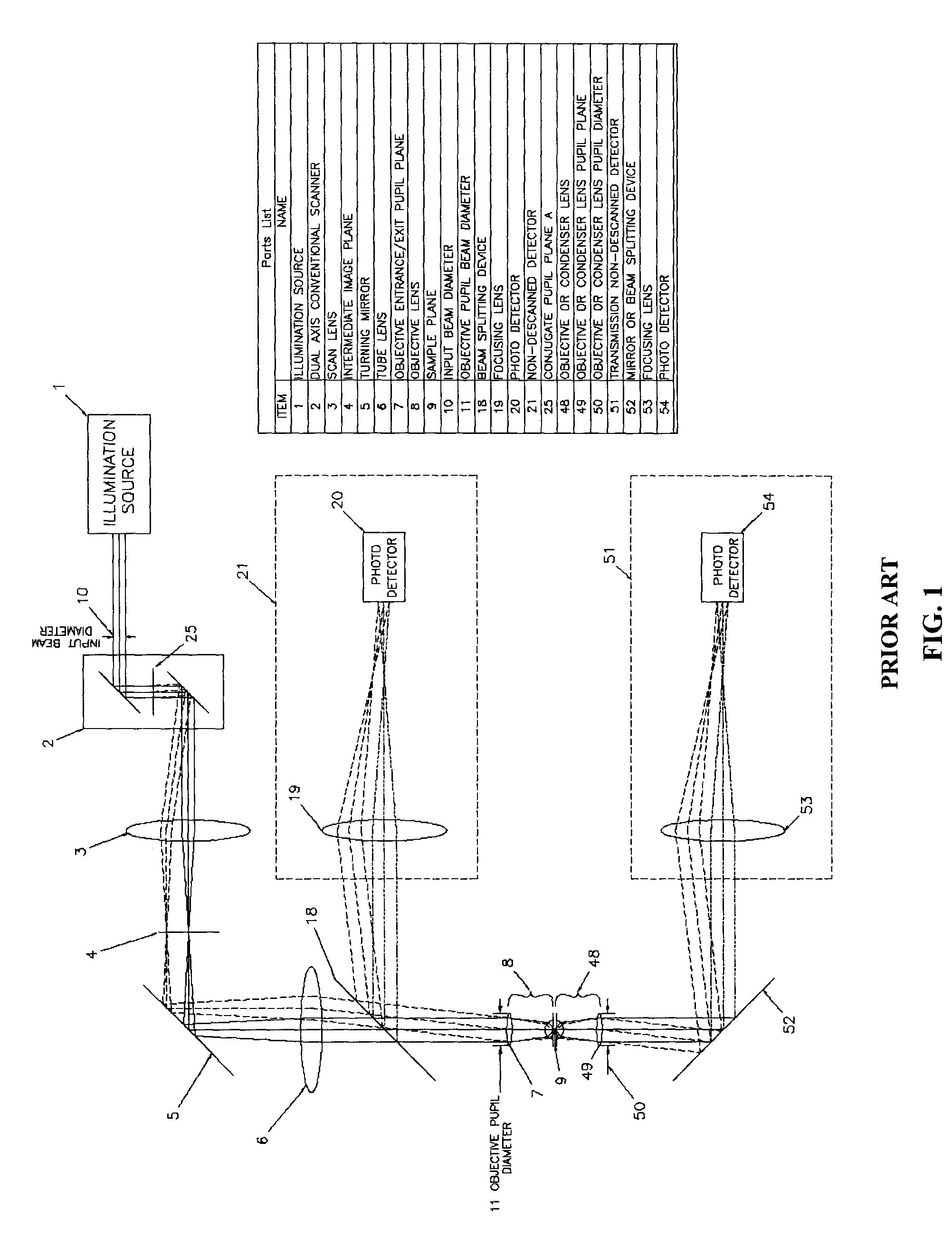
In a multiphoton scanning microscopy system the characteristics of the objective lens are the determining and limiting factor as to the accessible field of view and resolving capability of the entire system.
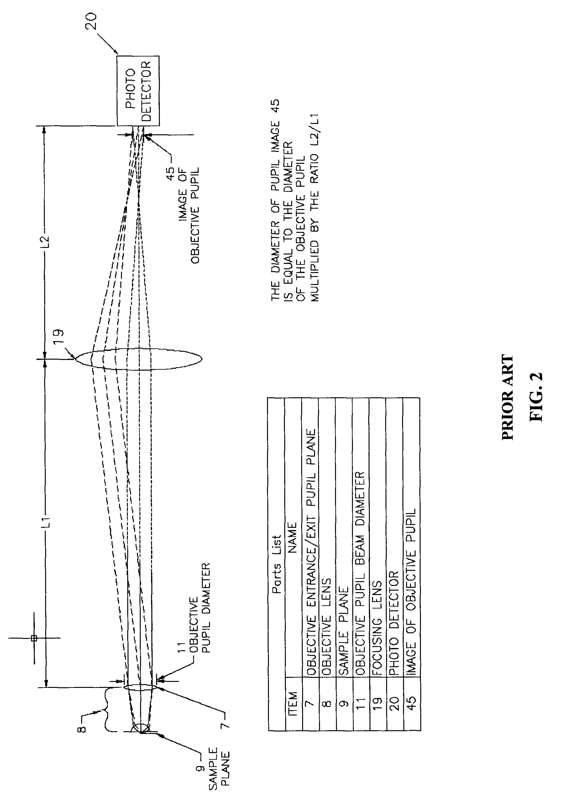
With the advent and implementation of large-pupil objective lenses (and equally so with condenser lenses) an inescapable geometric difficulty arises when attempting to transfer light from a relatively large objective pupil to a relatively small photodetector active area.
In the device shown in FIG. 3, the larger pupil image overfills the detector active area and a significant portion of the signal is wasted.
This loss of signal is a fundamental problem when using low-power, high NA objective lenses.
It also results in greater entry angles of the pupil image the photodetector.
In fact, if the translated distance is sufficiently large, the signal might miss the photodetector entirely.
Again there is a loss of efficiency.
These last three deficiencies all represent significant signal loss.
The same geometrical challenge arises with any photo-detector of minimum size when being coupled with these large aperture objective lenses.

Method used


Image

  • Apparatus for improving detection efficiency of multiphoton microscopy systems by focus compensation, pupil image division, and parallel pupil rearrangement
  • Apparatus for improving detection efficiency of multiphoton microscopy systems by focus compensation, pupil image division, and parallel pupil rearrangement
  • Apparatus for improving detection efficiency of multiphoton microscopy systems by focus compensation, pupil image division, and parallel pupil rearrangement

Examples


Embodiment Construction

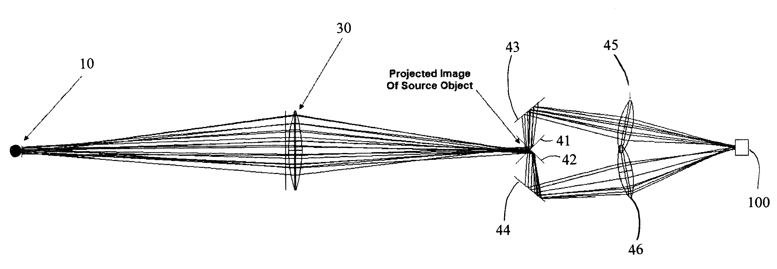
[0055]The present invention provides a novel apparatus and corresponding method to improve the distribution of the signal flux from a large aperture objective lens. The signal is divided (i.e. partitioned) and the partitioned sub-signals superimposed onto the active area of a small photodetector. The device is particularly suitable in the field of multiphoton microscopy in general and fluorescent and / or harmonic emission multiphoton microscopy in particular.

[0056]Thus, the invention is directed to an apparatus for spatial partitioning and redistribution of light emitted from a source object. The source object may be any object emitting electromagnetic radiation, such as a microscope objective lens pupil emitting signal light. (Again, “light” as used herein includes all forms of electromagnetic radiation—microwaves, UV, visible, IR, etc.) The simplest version of the invention comprises a first beam splitter. This beam splitter is configured to split the signal light into “n” independ...


PUM


Abstract

Disclosed is an apparatus for division and rearrangement of light from a source object. The apparatus splits the light from the source object, or image of the source object, and recombines it in a parallel, fashion to increase the efficiency of multiphoton microscopy in general and harmonic or fluorescence emission microscopy in particular. The apparatus includes a beam splitter configured to split a light beam into at least two independent light paths to yield a first light path and a second light path; a first beam focuser configured to direct and focus the first light path onto a focal plane; and a second beam focuser configured to direct and focus the second light path onto the same or different focal plane to which the first light path is focused; and wherein the first and second light paths may be superimposed upon one another at a common focal plane or directed independently to different positions.

Description

BACKGROUND[0001]In multiphoton microscopy, a beam of excitation light (usually pulsed infrared (IR) laser light) is brought to a focus within a specimen. Localized harmonic emission and / or multiphoton excited fluorescent emission is produced at this focus. Because of the non-linear dependency on flux intensity involved in these processes, the emitted light generated is highly localized at the point of focus and thus provides distinct information from only that point and none from the adjacent volume. In the case of two-photon fluorescent emission this signal light is approximately half the wavelength (twice the frequency) of the excitation beam. With 2nd and 3rd harmonic generation the wavelength of the signal light is exactly half or a third of the excitation wavelength. The microscopy system additionally includes a means of collecting this emitted light and projecting it onto any of a variety of photodetectors. The entire device is thus a very sensitive and spatially selective pro...

Claims


Application Information

Patent Timeline
Patent Type & Authority Patents(United States)
IPC IPC(8): H01J3/14
CPCG01J3/02G01J3/0208G01J3/021G01J3/0229G01J3/4406G02B21/002G02B21/16G01J3/36G02B2207/114
Inventor VOGT, WILLIAM I.
Owner PRAIRIE TECH
Learn More