
X-ray CT apparatus

a ct apparatus and x-ray technology, applied in the field of x-ray ct apparatus, can solve the problem of great error between the target sd in an image and the actual measured sd value, and achieve the effect of suppressing unnecessary x-ray radiation exposur

Active Publication Date: 2011-05-17
FUJIFILM HEALTHCARE CORP
View PDF5 Cites 24 Cited by
  • Summary
  • Abstract
  • Description
  • Claims
  • Application Information

AI Technical Summary

Benefits of technology

The present invention provides an X-ray CT apparatus that can control the modulation of X-ray irradiation dose using an elliptic model, regardless of the scanning region and the revolving position of the object. This ensures that the target image SD value is maintained in the set target SD value and the radiation exposure to the object is maintained in the minimum level necessary for reaching the target SD value. The X-ray CT apparatus includes an elliptic model generating function, an elliptic model adequacy determining function, and a radiation dose controlling function. The elliptic model is generated based on the maximum height and the area of the projection value profile of the scanning region obtained by performing scanogram projection on the object. The elliptic model adequacy determining function determines whether the elliptic model is adequate as a model for the scanning region or not. The corrected elliptic model generating function generates the corrected elliptic model based on the amount of characteristic of the projection value profile in the case that the elliptic model adequacy determining function determined that the elliptic model is inadequate as the model for the imaging region. The radiation dose controlling function controls the X-ray dose to be irradiated from the X-ray source based on the elliptic model or the corrected elliptic model.

Problems solved by technology

However, in the X-ray CT apparatus disclosed in JP-A-2001-276040, though the target SD value in an image matches well with the actually measured SD value in the case of scanning the region having comparatively homogeneous X-ray attenuation coefficient such as abdominal region, there are cases that a great error can be caused between the target SD in an image and the actually measured SD value when scanning the region having inhomogenous X-ray attenuation coefficient such as a chest region.

Method used


Image

  • X-ray CT apparatus
  • X-ray CT apparatus
  • X-ray CT apparatus

Examples


Embodiment Construction

[0029]The best mode for carrying out the present invention will be described below based on the attached diagrams.

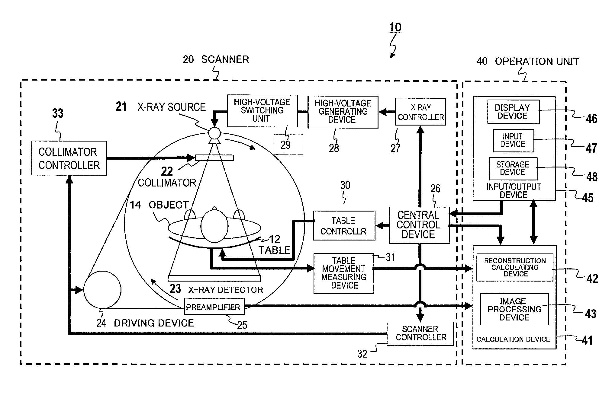
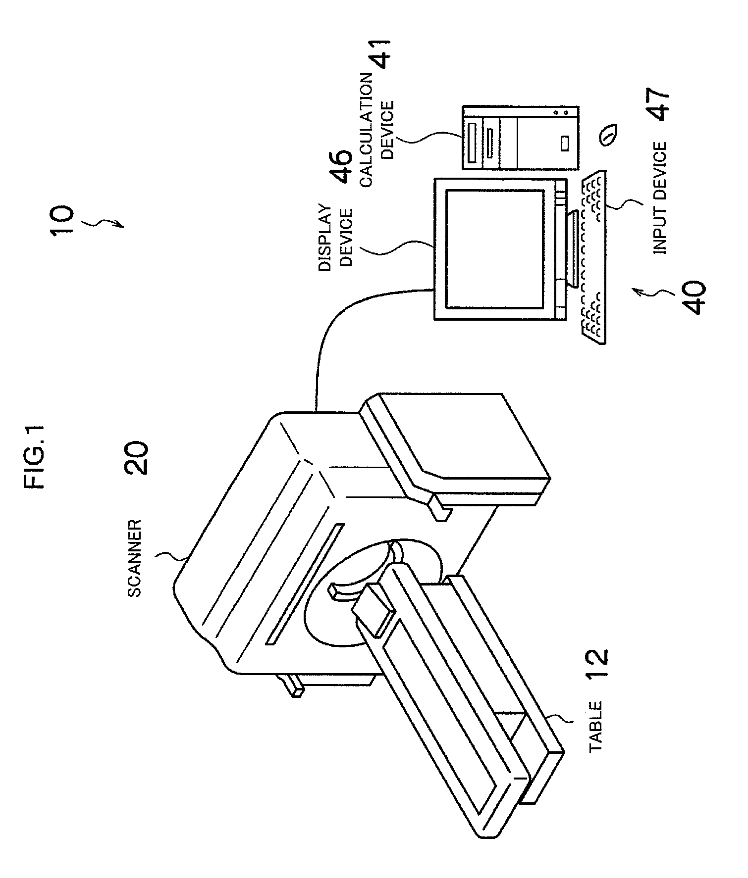
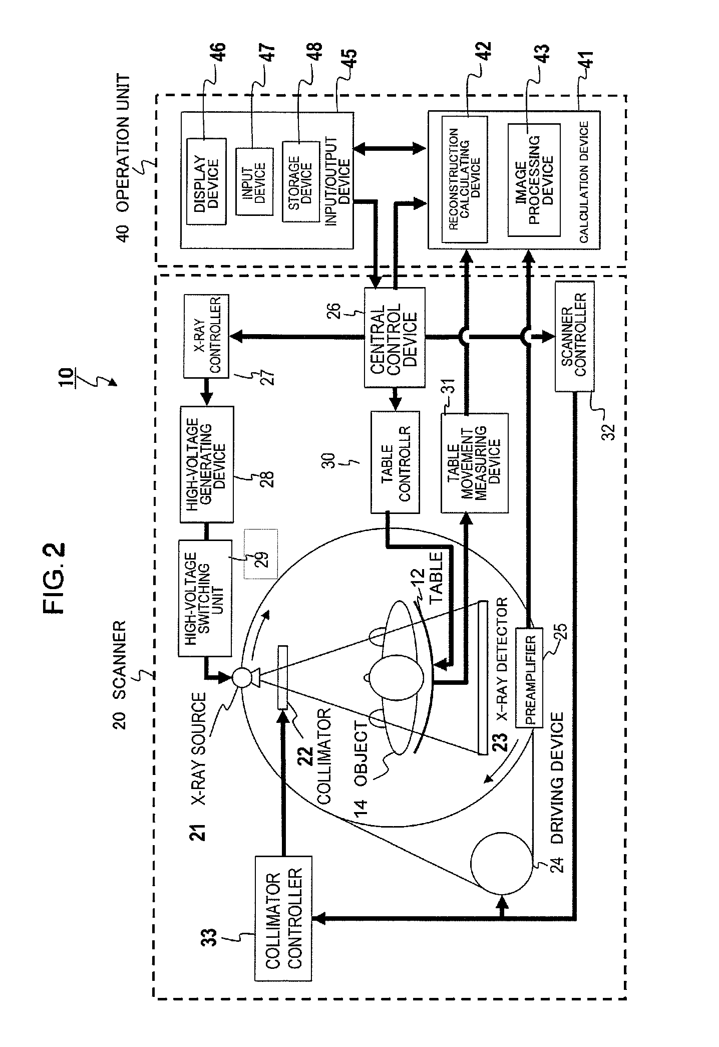
[0030]The configuration of the X-ray CT apparatus to which the present invention is applied will be described referring to FIG. 1 and FIG. 2.

[0031]As shown in FIG. 1, an X-ray CT apparatus 10 is mainly configured by:[0032]a table 12 for moving an object to be examined;[0033]a scanner 20 for scanning the object;[0034]a calculation device 41 for processing the data acquired from the X-ray detector provided in the scanner 20 and reconstructing a tomographic image;[0035]a display device 46 for displaying the reconstructed tomographic image; and[0036]an input device 47 configured by devices such as a mouse and a keyboard, for inputting measurement / reconstruction parameters such as table moving velocity information or reconstruction positions.

[0037]The block configuration of the X-ray CT apparatus 10 whose external view is shown in FIG. 1 is shown in FIG. 2. This X-ray CT appa...


PUM


Abstract

An X-ray CT apparatus acquires a scanogram of an object to be examined, generates an ellipse model having an X-ray attenuation coefficient equivalent to that of water and approximated to a tomographic image of the obtained imaged portion from the feature quantity of the projection value profile, determines whether or not the generated elliptic model is adequate as a model of the imaged portion from another feature quantity with respect to the projection value profile, generates a corrected elliptic model according to yet another feature quantity with respect to the projection value profile if the elliptic model is determined to be inadequate, and controls the modulation of the tube current in an X-ray source so that a predetermined target SD value is maintained in any scanning position when a tomographic image is reconstructed according to X-rays transmitted through the object by using the elliptic model or the corrected elliptic model.

Description

TECHNICAL FIELD[0001]The present invention relates to upgrading of an X-ray CT apparatus that controls the modulation of X-ray dose to be irradiated to an object to be examined by using an elliptic model which is approximated to a human body, in order to achieve the target SD (Standard Deviation) in an image with respect to the image data of the object.BACKGROUND ART[0002]As for the method for evaluating noise (photon noise) of an X-ray CT apparatus, SD in an image has been used. The SD in an image indicates dispersion degree from the average value of pixel values, and the higher the noise is the greater the SD value becomes. Particularly, in the case of observing (diagnosing) a region in the object wherein the difference in CT values are small, i.e. CT values are comparatively homogeneous, it is necessary to reduce noise, i.e. to suppress SD value of the image.[0003]One of the methods for reducing noise is to increase the number of photons (volume of information). It is known that ...

Claims


Application Information

Patent Timeline
Patent Type & Authority Patents(United States)
IPC IPC(8): A61B6/00
CPCA61B5/4869A61B6/542A61B6/50A61B6/505
Inventor GOTO, TAIGAHIROKAWA, KOICHIIRIE, TOSHIYUKI
Owner FUJIFILM HEALTHCARE CORP
Learn More