Supercharge Your Innovation With Domain-Expert AI Agents!

Displacement measurement method and apparatus, strain measurement method and apparatus, elasticity and visco-elasticity constants measurement apparatus, and the elasticity and visco-elasticity constants measurement apparatus-based treatment apparatus

a displacement measurement and displacement vector technology, applied in the field of displacement measurement methods and apparatuses, can solve the problems of inability to use techniques, inability to meet the needs of past measurement techniques, and difficulty in achieving the effect of reducing the amount of calculation, simplifying the calculation process, and improving the measurement accuracy of displacement vector distribution

Active Publication Date: 2011-05-24
CHIKAYOSHI SUMI
View PDF9 Cites 11 Cited by
  • Summary
  • Abstract
  • Description
  • Claims
  • Application Information

AI Technical Summary

Benefits of technology

This approach enables more accurate measurement of displacement vectors and strain tensors, improving the assessment of tissue mechanical properties with reduced complexity and increased spatial resolution, even in the presence of internal, uncontrollable mechanical sources.

Problems solved by technology

If degeneration occurs on the part of region, the relating physical properties also change; thus resulting severe limitations of the temperature measurement.
Other disadvantage is that the past measurement technique needs many independent deformation fields generated by mechanical sources outside the target body.
However, if there exist internal mechanical sources or mechanical sources are uncontrollable, the technique becomes unavailable.
However, as the classical tissue displacement measurement methods assume tissue being deformed only in the axial (beam) direction, when tissue also moves in lateral (scan) direction, the classical method has low axial measurement accuracy.
However, strictly speaking, measurement accuracy of actual 3D tissue displacement becomes low because the method can measure by 2D processing of echo signals two displacement components or by 1D processing one displacement component.
Thus, the low lateral measurement accuracy degrades the 3D displacement vector measurement and the 3D strain tensor measurement.
Thus, measurement process had become complex one.

Method used


Image

  • Displacement measurement method and apparatus, strain measurement method and apparatus, elasticity and visco-elasticity constants measurement apparatus, and the elasticity and visco-elasticity constants measurement apparatus-based treatment apparatus
  • Displacement measurement method and apparatus, strain measurement method and apparatus, elasticity and visco-elasticity constants measurement apparatus, and the elasticity and visco-elasticity constants measurement apparatus-based treatment apparatus
  • Displacement measurement method and apparatus, strain measurement method and apparatus, elasticity and visco-elasticity constants measurement apparatus, and the elasticity and visco-elasticity constants measurement apparatus-based treatment apparatus

Examples


Embodiment Construction

[0070]The following is explanation in detail of conduct forms of the present invention with referring to figures.

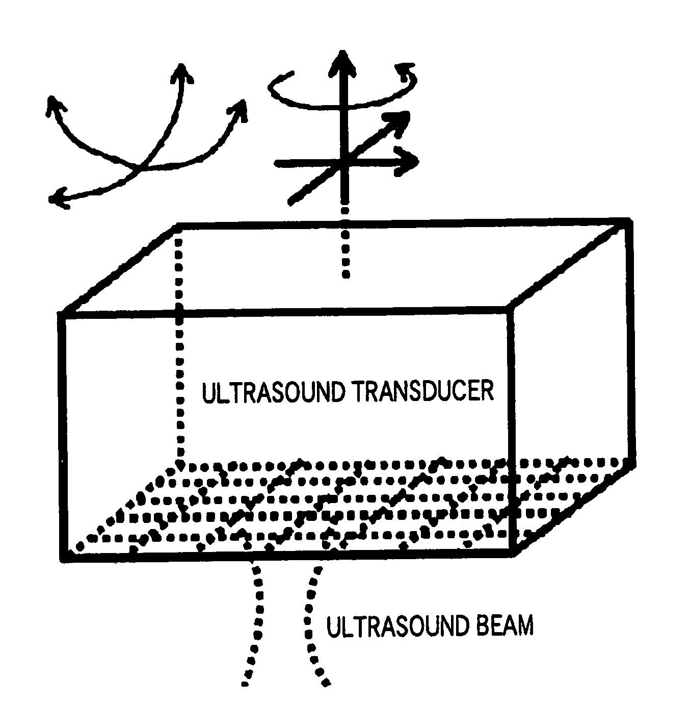
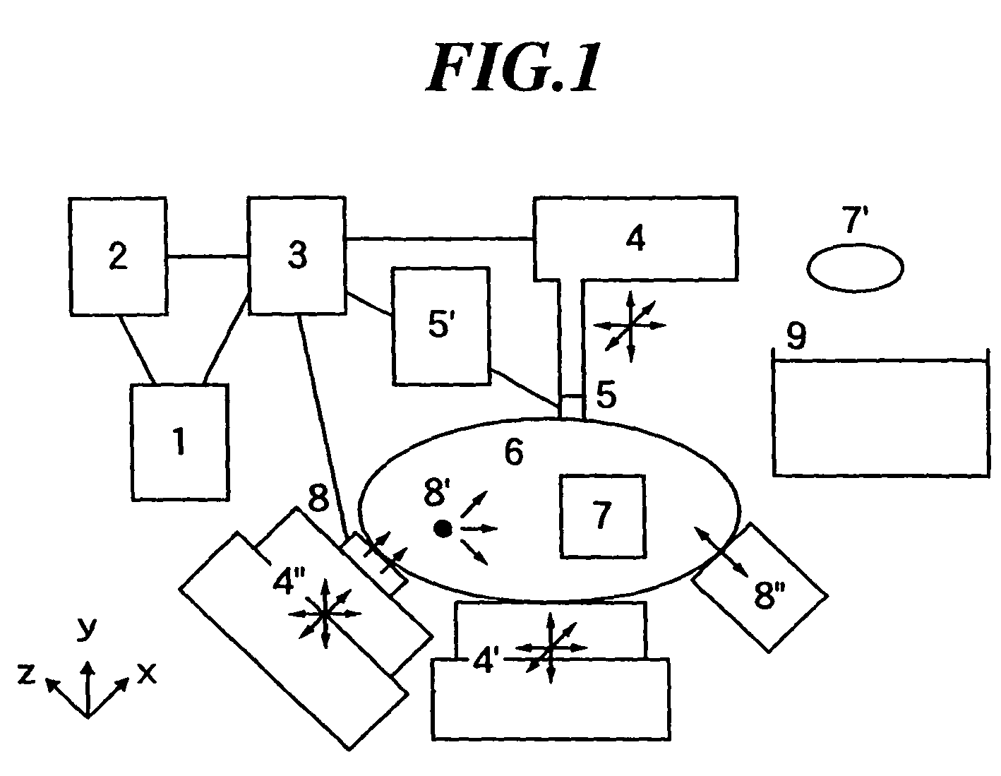
[0071]FIG. 1 shows a schematic representation of a global frame of displacement vector and strain tensor measurement apparatus, and elasticity and visco-elasticity constants measurement apparatus, related to one of conduct forms of the present invention. This apparatus measures in 3D, 2D, or 1D ROI 7 set in measurement object 6 displacement vector component distributions, strain tensor component distributions, their time-space partial derivative distributions, etc. to obtain strain tensor field, strain rate tensor field, acceleration vector etc., from which this apparatus measures following constant distributions, i.e., elastic constants such as shear modulus, Poisson's ratio, etc., visco elastic constants such as visco shear modulus, visco Poisson's ratio, etc., delay times or relaxation times relating these elastic constants and visco elastic constants, or density.

[0072...


PUM


Abstract

The present invention provides elastic constant and visco elastic constant measurement apparatus etc. for measuring in the ROI in living tissues elastic constants such as shear modulus, Poisson's ratio, Lame constants, etc., visco elastic constants such as visco shear modulus, visco Poisson's ratio, visco Lame constants, etc. and density even if there exist another mechanical sources and uncontrollable mechanical sources in the object. The elastic constant and visco elastic constant measurement apparatus is equipped with means of data storing 2 (storage of deformation data measured in the ROI 7 etc.) and means of calculating elastic and visco elastic constants 1 (calculator of shear modulus etc. at arbitrary point in the ROI from measured strain tensor data etc.), the means of calculating elastic and visco elastic constants numerically determines elastic constants etc. from the first order partial differential equations relating elastic constants etc. and strain tensor etc.

Description

[0001]This is a divisional of application Ser. No. 10 / 326,526 filed Dec. 23, 2002. The entire disclosure of the prior application, application Ser. No. 10 / 326,526 is considered part of the disclosure of the accompanying Divisional application and is hereby incorporated by reference.[0002]This invention claims priority to prior Japanese Patent Applications 2001-389484, filed Dec. 21, 2001, 2002-10368, filed Jan. 18, 2002, JP2002-123765, filed Apr. 25, 2002, JP2002-143145, filed May 17, 2002, JP2002-176242, filed Jun. 17, 2002, JP2002-178265, filed Jun. 19, 2002, JP2002-238434, filed Aug. 19, 2002, JP2002-240339, filed Aug. 21, 2002, JP2002-241647, filed Aug. 22, 2002, and JP2002-256807, filed Sep. 2, 2002, the disclosures of which all are incorporated herein by reference.BACKGROUND OF THE INVENTION[0003]1. Field of the Invention[0004]The present invention relates to an apparatus and method for low-destructively (low-invasively) measuring mechanical properties within object such as st...

Claims


Application Information

Patent Timeline
Patent Type & Authority Patents(United States)
IPC IPC(8): G01D1/16A61B8/08G01S15/89
CPCA61B5/0048A61B8/08A61B8/485G01S15/899G01S7/52042G01S15/8979A61B5/015G01S15/8977A61B8/488A61B5/0051A61B5/0053A61N7/02
Inventor SUMI, CHIKAYOSHI
Owner CHIKAYOSHI SUMI
Features
  • R&D
  • Intellectual Property
  • Life Sciences
  • Materials
  • Tech Scout
  • Unparalleled Data Quality
  • Higher Quality Content
  • 60% Fewer Hallucinations
Learn More