Methods and apparatus for well construction

a well and equipment technology, applied in the direction of wellbore/well accessories, sealing/packing, insulation, etc., can solve problems such as problems, and achieve the effect of improving expansion flexibility and sufficient deformation for expansion

Inactive Publication Date: 2011-05-24
SCHLUMBERGER TECH CORP
View PDF18 Cites 8 Cited by
  • Summary
  • Abstract
  • Description
  • Claims
  • Application Information

AI Technical Summary

Benefits of technology

[0014]It is also preferred to heat the sleeve prior to expansion to improve flexibility. After heating and expansion, the sleeve can be cooled so as to set the sleeve in its expanded state.
[0025]Downhole temperatures may be sufficiently high that the sleeve already has sufficient deformability for expansion and it is merely necessary to pump in fluid to cause expansion. Further softening of the sleeve may be used to improve flexibility for expansion.

Problems solved by technology

However, problems can occur if drilling mud remains in the borehole when the cement is placed, or microannuli form around the casing and / or borehole wall.
There are various well-known problems associated with conventional cementing operations.

Method used


Image

  • Methods and apparatus for well construction
  • Methods and apparatus for well construction
  • Methods and apparatus for well construction

Examples


Embodiment Construction

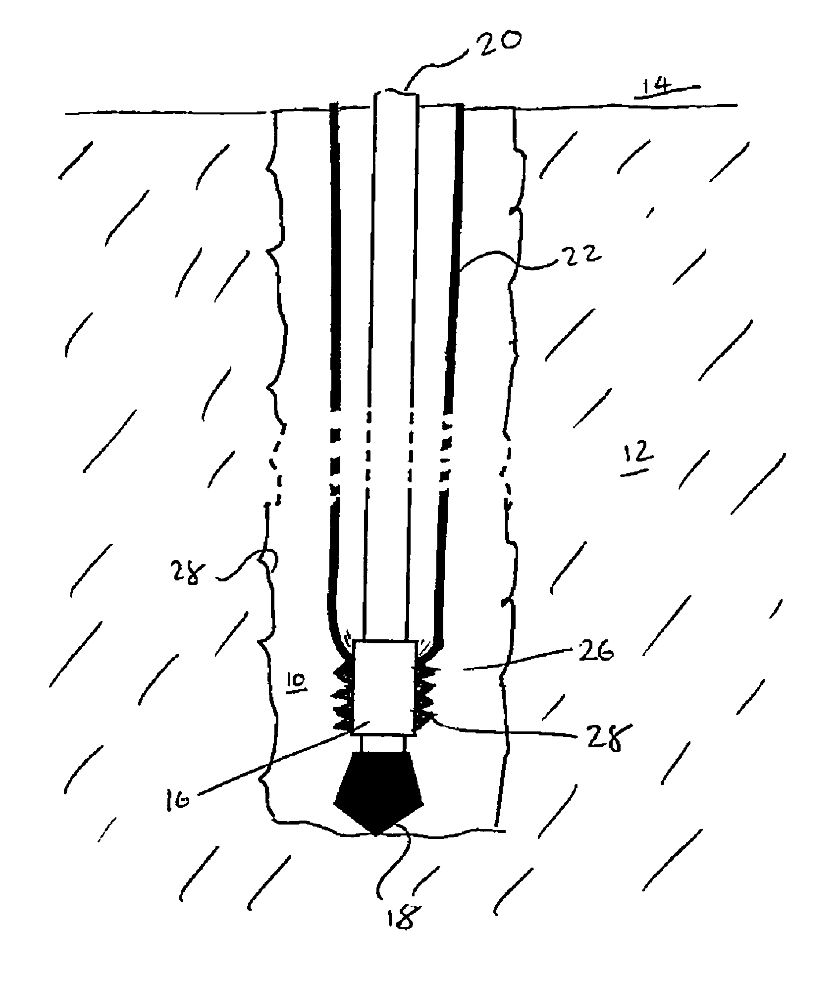
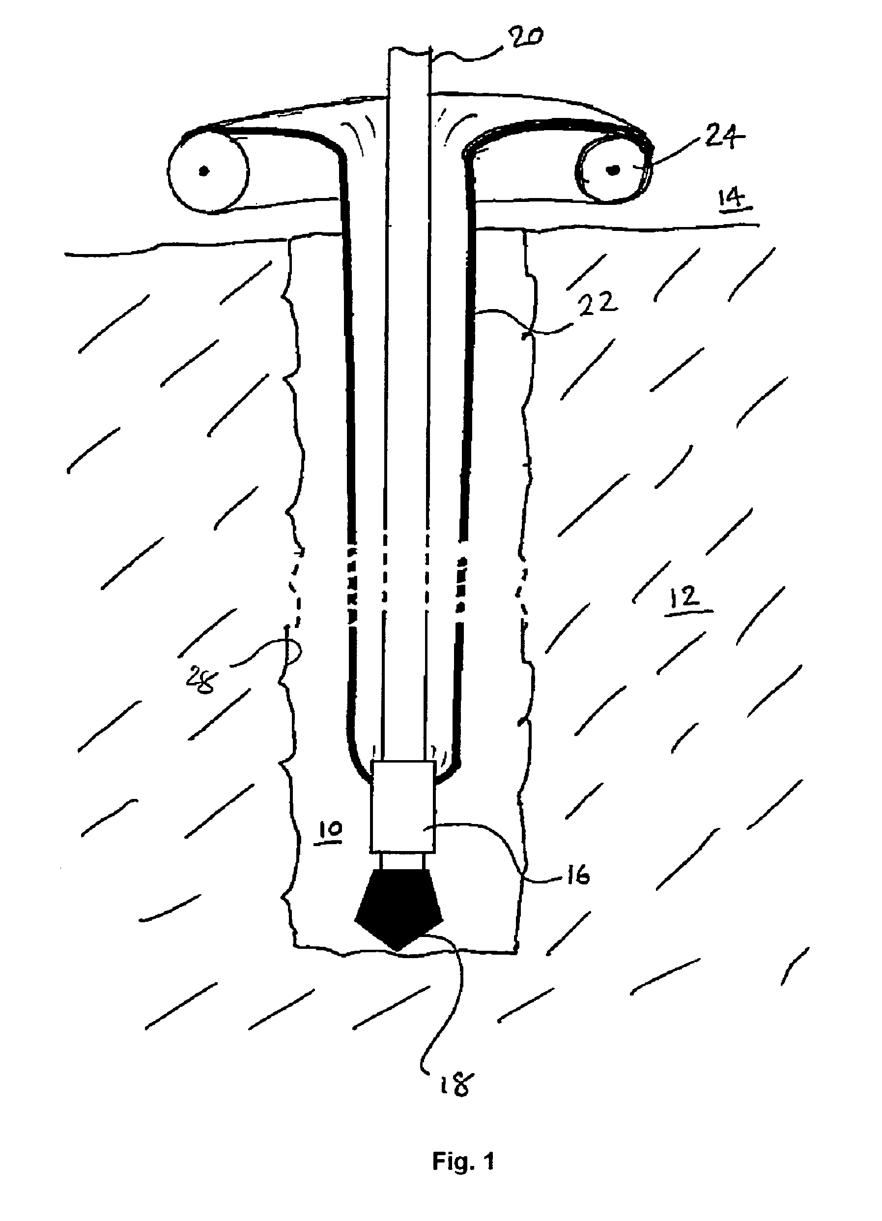
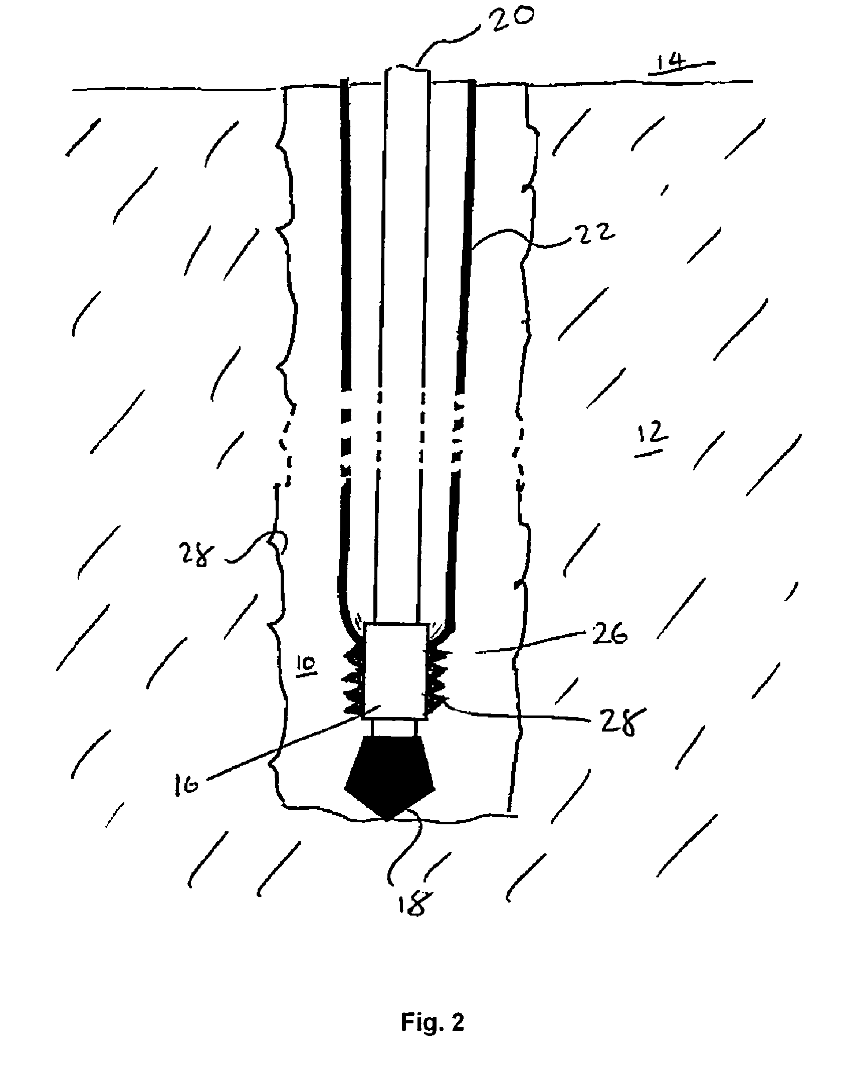
[0030]Referring now to the drawings, FIG. 1 shows a first embodiment of an apparatus according to the invention that can be used to line a borehole 10 drilled through underground formations 12 from the surface 14. The drilling operation is conducted using a drilling apparatus 16 carrying, inter alia, a drill bit 18. The drilling apparatus 16 is carried on the end of a drill string 20 that extends through the borehole 10 from the surface 14. The drill bit 18 is rotated by rotation of the drill string 20 and / or by use of a downhole motor forming part of the drilling apparatus 16. A flexible, tubular liner sleeve 22 extends concentrically around the drill string 20 through the borehole 10. The sleeve 22 is connected around the outside of the top of the drill string 20, at the upper opening of the borehole 10 by a spool 24 on which the sleeve is rolled. The sleeve 22 is connected at the lower end of the drill string 20 at the drilling assembly 16.

[0031]As the drilling progresses, the dr...


PUM


Abstract

A method of constructing a borehole drilled with a drilling apparatus (16), the method comprises: connecting a flexible tubular liner sleeve (22) around the outside of the drilling apparatus and connecting the sleeve around an upper opening of the borehole so as to pass into the borehole; progressively extending the sleeve into the borehole as drilling progresses while maintaining connection to the drilling apparatus and borehole opening; at a predetermined point in the drilling, expanding the sleeve so as to contact the borehole wall; and setting the sleeve so as to be fixed to the borehole wall after expansion. Apparatus for use in such a method comprises: a flexible, expandable sleeve (22); a first connector for connecting the sleeve around the outside of a drilling assembly; and a second connector for connecting the sleeve around the opening of the borehole; wherein the sleeve is arranged to extend through the borehole between the connectors as drilling progresses.

Description

TECHNICAL FIELD[0001]This invention relates to methods and apparatus for zonal isolation and borehole stabilisation that are particularly applicable to boreholes such as oil and gas wells, or the like. They provide techniques that can be used in addition to or as an alternative to conventional well completion techniques such as cementing.BACKGROUND ART[0002]Completion of boreholes by casing and cementing is well known. Following drilling of the borehole, a tubular casing, typically formed from steel tubes in an end to end string is placed in the borehole and cement is pumped through the casing and into the annulus formed between the casing and the borehole wall. Once set, the cemented casing provides physical support for the borehole and prevents fluid communication between the various formations or from the formations to the surface (zonal isolation). However, problems can occur if drilling mud remains in the borehole when the cement is placed, or microannuli form around the casing...

Claims


Application Information

Patent Timeline
Patent Type & Authority Patents(United States)
IPC IPC(8): E21B7/00
CPCE21B43/103E21B7/20
Inventor JEFFRYES, BENJAMINBAILEY, LOUISECOOPER, IAINMAITLAND, GEOFFREYGUILLOT, DOMINIQUE
Owner SCHLUMBERGER TECH CORP
Why Eureka
Try Eureka