Actuator

a technology of actuators and actuators, applied in the field of actuators, can solve problems such as difficulty in adjusting the amount of kinetic energy absorption

Active Publication Date: 2011-05-24
TOYODA GOSEI CO LTD
View PDF7 Cites 27 Cited by
  • Summary
  • Abstract
  • Description
  • Claims
  • Application Information

AI Technical Summary

Benefits of technology

[0010]The invention has been made with view to solving the problem inherent in the related art, and an object thereof is to provide an actuator which can restrict a backward movement of a piston rod after the actuator has been activated in a stable manner and can easily deal with a change in bending rigidity of a piston rod which supports a receiving member when it is required.
[0026]As this occurs, the lock ring is diametrically expanded in such a way as to be restored from the state in which the lock ring is diametrically contracted to be accommodated in the accommodating groove on the piston portion and comes into abutment with the locking and restricting surface of the locking stepped portion at its backward moving side surface and with the outer circumferential restricting surface of the locking stepped portion at its outer circumferential surface to thereby be fixed to the locking stepped portion in such a way as to be restricted with respect to its backward movement and diametrically expanding movement, and the inner circumferential side portion of the lock ring is projecting further towards the axis center side of the main body portion on the inner circumferential surface side of the main body portion of the cylinder. In other words, in this state, the lock ring is projecting towards the inner circumferential side of the main body portion at the portion on the cylinder where the locking stepped portion is disposed so as to constitute the locking edge for locking the accommodating groove on the piston portion of the cylinder. In addition, since the wire material forming the lock ring has the circular cross section and even though the portion of the wire material in the locking state is twisted in such a manner as to rotate about the vicinity of the center of the circular cross section, the lock ring is not changed in such a manner as to reduce the projecting amount towards the inner circumferential side of the main body portion, the locking edge made up of the lock ring allows the taper restricting surface of the accommodating groove to come into abutment therewith in a stable manner so as to lock the piston portion of the piston rod, thereby making it possible to implement locking so as to restrict the backward movement of the piston rod even though the accommodating groove moves forwards together with the piston portion to interfere with the locking edge again.
[0028]In addition, in the actuator according to the invention, even though the outside diametrical dimension of the support rod portion is changed so as to change the bending rigidity thereof, although the inside diametrical dimension of the insertion hole for the support rod portion in the distal end wall portion on the cylinder side needs to be adjusted, the configurations of the piston portion including the accommodating groove, the lock ring and the cylinder side locking stepped portion do not have to be changed but can continue to be used, the attempt to change the bending rigidity of the support rod portion or the piston rod being thereby dealt with easily.
[0029]Consequently, with the actuator according to the invention, the backward movement of the piston rod after it has moved forwards can be restricted in a stable manner, and the attempt to change the bending rigidity of the piston rod which supports the receiving member can easily be dealt with.
[0030]In addition, in the actuator according to the invention, the lock ring is made of the wire material having a circular cross section. Thus, even though the lock ring accommodated in the accommodating groove slides over the inner circumferential surface of the main body portion of the cylinder when the actuator is activated, only the wire-like thin portion extending in the outer circumferential surface of the lock ring in the circumferential direction is brought into line contact with the inner circumferential surface of the main body portion, whereby the piston rod can move forwards within the cylinder in a smooth manner with suppressed frictional resistance.
[0032]In the configuration described above, in the event that when the actuator is activated to operate, the piston rod moves forwards and the lock ring expands diametrically to thereby enter the locking stepped portion from the accommodating groove, the outer circumferential surface of the lock ring is brought into abutment with the outer circumferential restricting surface of the locking stepped portion, and the backward moving side surface of the lock ring is brought into abutment with the locking and restricting surface of the locking stepped portion in such a manner as to restrict the backward movement of the lock ring. Then, as this occurs, the portion of the backward moving side surface of the lock ring which is brought into abutment with the locking and restricting surface of the locking stepped portion can ensure the state in which a backward moving side apex portion is in abutment with the area of the locking and restricting surface itself which lies in the vicinity of the inner circumferential surface side edge of the main body portion. Namely, the backward moving side apex portion of the wire material having a circular cross section and making up the lock ring is brought into abutment with the locking and restricting surface which confronts the backward moving direction at right angles to thereby restrict the backward movement of the lock ring. Therefore, even though the compression stress applied to the piston rod is high, the locking and restricting surface of the locking stepped portion can receive the piston rod with the lock ring interposed therebetween. Further, in the event that the diametrically expanded lock ring is brought into abutment with the outer circumferential restricting surface of the locking stepped portion on the outer circumferential surface thereof, the center of the cross section of the wire material which makes up the lock ring comes to be disposed in the area of the locking and restricting surface from the inner circumferential surface of the main body portion along the direction which is at right angles to the axis of the main body portion. Due to this, even though the lock ring interferes with the taper restricting surface and attempts to return to the accommodating position in the accommodating groove (the initial accommodating position before the activation of the actuator), on the backward moving side to which the lock ring attempts to move, the locking and restricting surface lies squared against the lock ring with the backward moving side apex portion of the wire material having a circular cross section and making up the lock ring kept stationary to restrict the backward movement of the lock ring. Therefore, the behavior of the lock ring attempting to be restored to the accommodating position in the accommodating groove is prevented in an ensured manner.

Problems solved by technology

Because of this, in the event that the C ring behaved as being diametrically expanded in a radially outward direction of the cylinder between the confronting taper surfaces when locking took place, it became difficult to restrict the diametrical expansion of the C ring due to a lower surface side of the cylinder side accommodating groove being formed in such a manner as to be diametrically expanded in an upward direction, leading to a fear that the C ring was allowed to pop out from the interior of the fitting groove on the piston rod to thereby easily cancel the locked state.
As this occurs, a minute sliding gap exists in the location of the piston rod which slides within the cylinder, and this gap is combined with an action of the piston rod in which the piston rod is inclined in the direction which is at right angles to the axis of the piston rod within the cylinder, whereby with no action taken to cope with this, there tends to be caused a fear that the C ring moves in the way described above when locking takes place, as a result of which the cancellation of the locked state is facilitated further.
Thus, the adjustment of kinetic energy absorption amount has not been easy to be dealt with.

Method used


Image

  • Actuator
  • Actuator
  • Actuator

Examples


Embodiment Construction

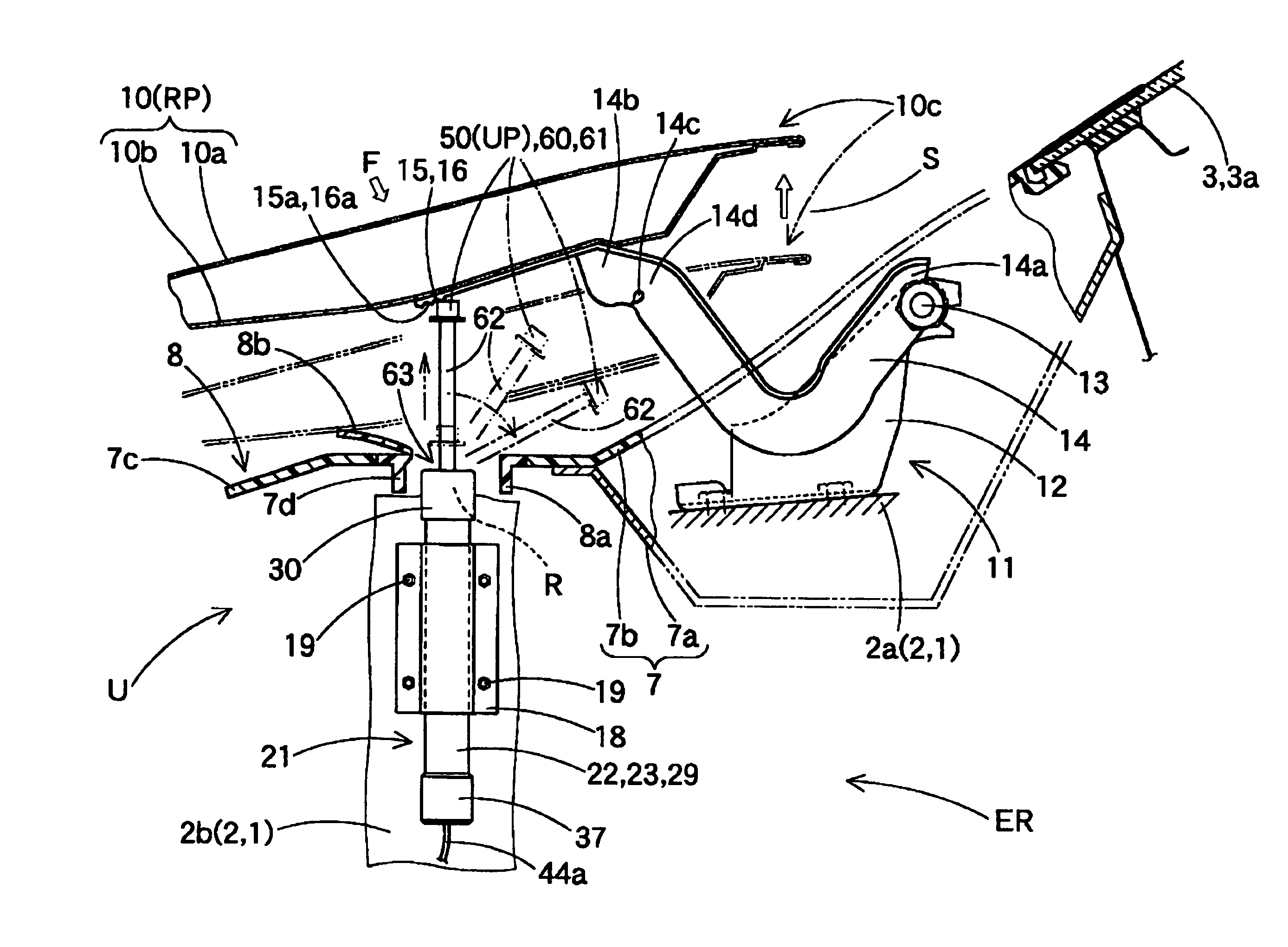
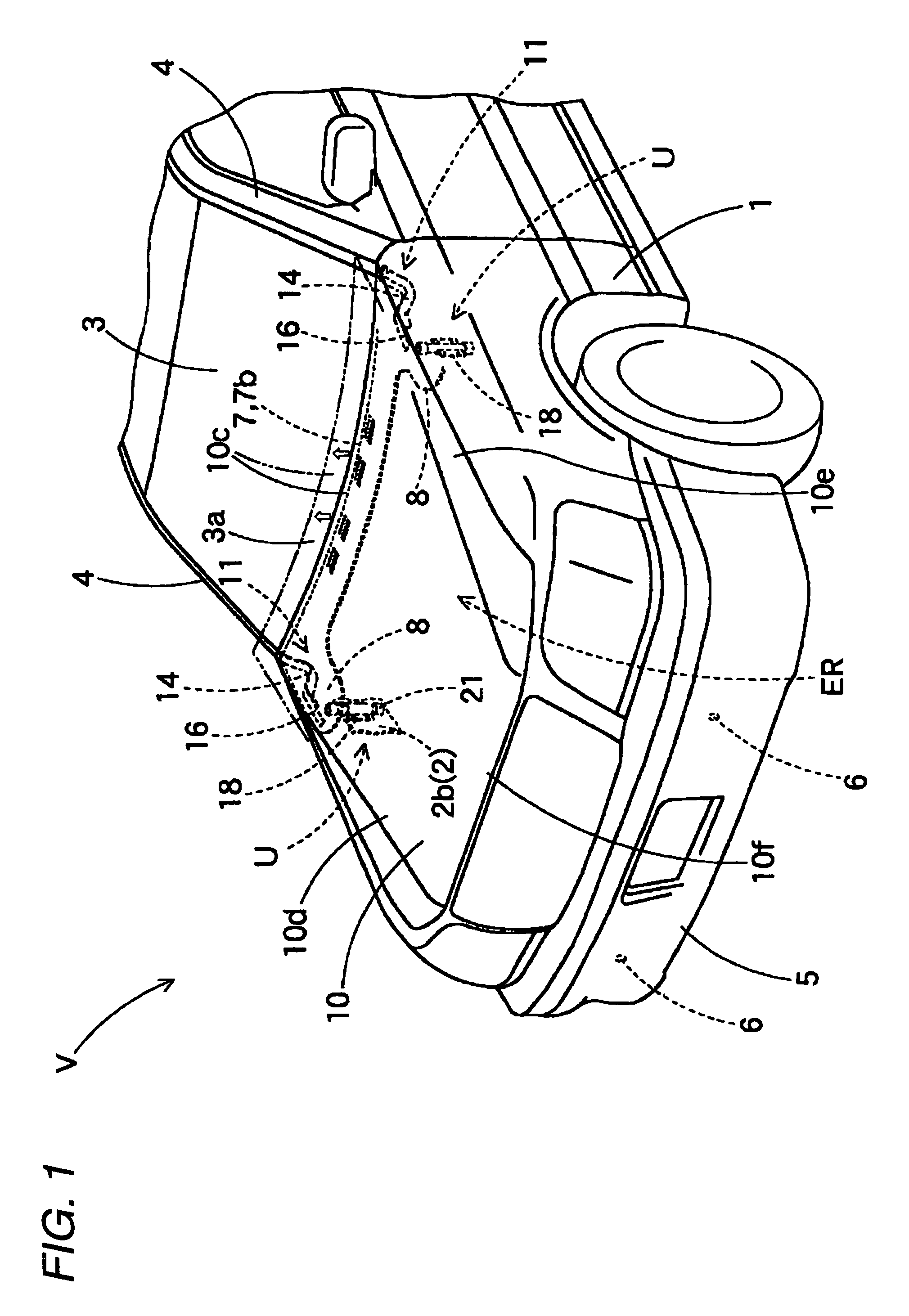
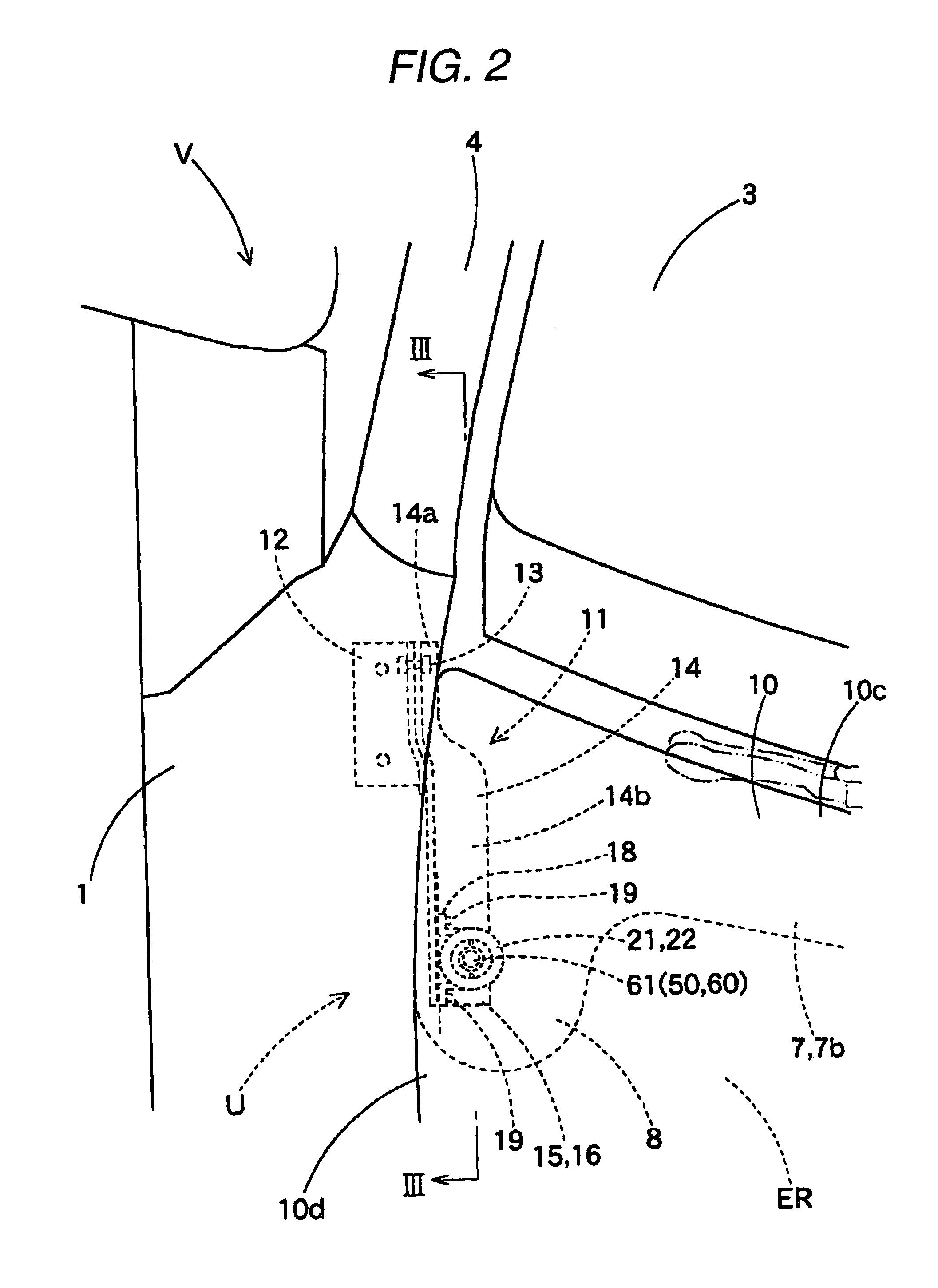
[0042]Hereinafter, an embodiment of the invention will be described based on accompanying drawings. Automotive safety equipment to which an actuator 2 of this embodiment is applied is a hood lift-up apparatus (hereinafter, referred to simply as a “lift-up apparatus”) U. This lift-up apparatus U is, as is shown in FIGS. 1, 2, such as to be disposed in positions lying near a left-hand edge 10d and a right-hand edge 10e on a rear end 10c side of a hood panel 10 of a vehicle V, respectively. Each lift-up apparatus U includes an actuator 21 and a receiving seat 16 which is disposed on a lower surface of the hood panel 10 at the rear end 10c. In addition, as is shown in FIGS. 3, 4, in the lift-up apparatus U, when it is activated, the actuator 21 raises a piston rod 50 to thereby raise the rear end 10c of the hood panel 10 in a lift-up manner via the receiving seat 16.

[0043]In addition, when used in this specification, unless described otherwise, front-rear or longitudinal and up-down or ...


PUM


Abstract

When activated, an actuator causes a piston rod in a cylinder to move forwards so as to support a receiving member for receiving an object to be protected. A lock mechanism for restricting a backward movement of the piston rod includes a lock ring which is accommodated in an accommodating groove on a piston portion and a locking stepped portion on the cylinder side. The locking stepped portion includes a locking and restricting surface and an outer circumferential restricting surface. A taper restricting surface in the accommodating groove on the piston portion is brought into abutment with an inner surface on a forward moving side of the lock ring which is being diametrically expanded as a result of the piston rod having moved forwards and is in abutment with the locking and restricting surface and the outer circumferential restricting surface of the locking stepped portion, whereby the backward movement of the piston rod is restricted by making use of the lock ring which is restricted in the locking stepped portion.

Description

BACKGROUND OF THE INVENTION[0001]1. Field of the Invention[0002]The present invention relates to an actuator for use in automotive safety equipment and more particularly to, for example, an actuator for use in an operation such as one for raising a hood panel of an automobile when receiving a pedestrian as an object to be protected by the hood panel.[0003]2. Related Art[0004]Conventionally, as actuators for safety equipment mounted on motor vehicles, there have been actuators for raising a rear end side of a hood panel so as to receive a pedestrian by the hood panel itself by making use of energy absorption taking place when the hood panel is plastically deformed (for example, refer to JP-A-2004-330912).[0005]The actuators were configured as actuators of a piston cylinder type in which gas generated when a gas generator was activated was used as a drive source, so as to be put into operation quickly. In the actuators so configured, gas generated as working fluid when the gas generat...

Claims


Application Information

Patent Timeline
Patent Type & Authority Patents(United States)
IPC IPC(8): B60R21/34F15B15/26B60R21/38B62D25/10F15B15/19
CPCB60R21/38
Inventor HAYASHI, TAKEKIAOKI, MASASHIMATSUURA, HIROKAZUKITTE, HAJIME
Owner TOYODA GOSEI CO LTD
Why Eureka
Try Eureka