Multi-beam ion/electron spectra-microscope

a multi-beam ion/electron spectra-microscope technology, applied in the field of focused beam analytic instruments, can solve problems such as difficulty in achieving short working distances

Inactive Publication Date: 2011-05-24
NAT UNIV OF SINGAPORE
View PDF22 Cites 20 Cited by
  • Summary
  • Abstract
  • Description
  • Claims
  • Application Information

AI Technical Summary

Benefits of technology

It is a first object of this invention to provide a multi-beam charged particle instrument that can simultaneously focus electrons and a variety of ions on a material sample.
It is a fifth object of the present invention to provide such an instrument wherein an electron beam and an ion beam can be operated in parallel to provide a highly dispersive mass / energy spectrometer, providing, thereby, far more advantages and capabilities than a separately operating SEM and mass spectrometer.
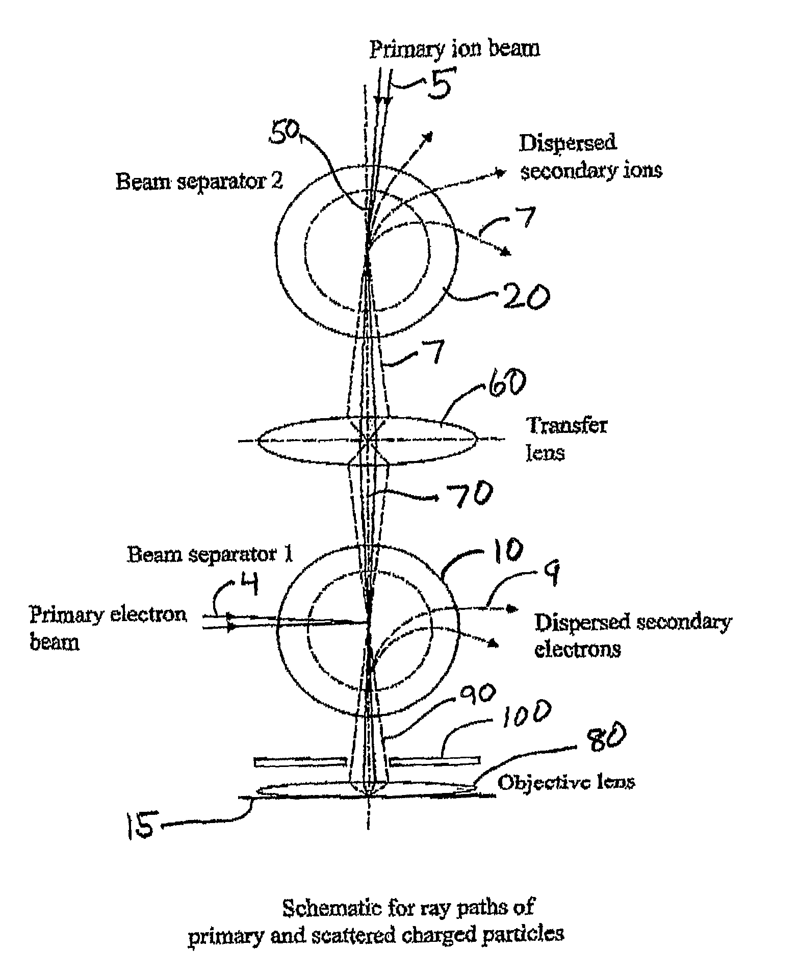
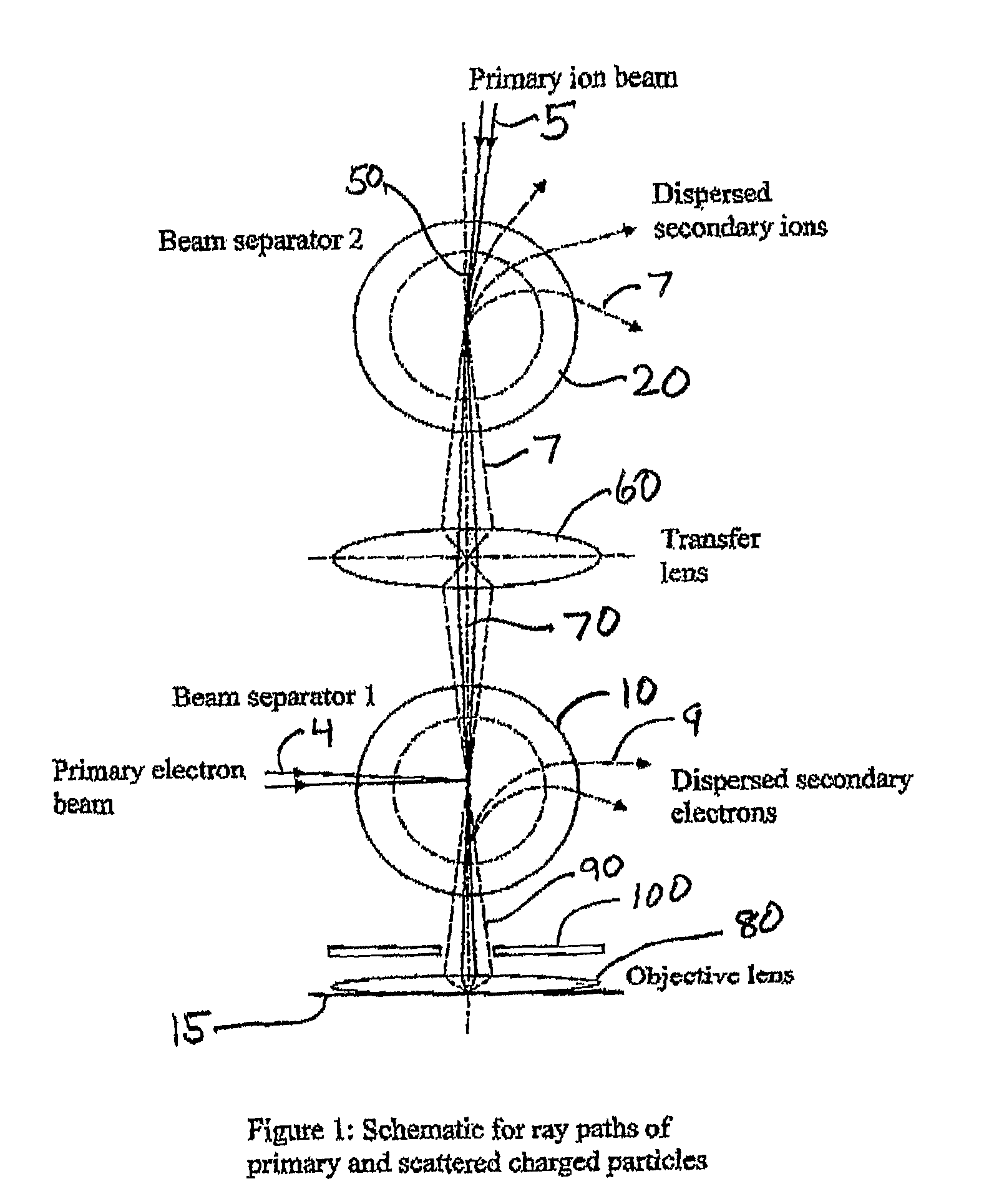
To accommodate both types of charged particles (electrons and ions) here are two beam separators, one for electron beams (beam separator 1 (10)) and one for ion beams (beam separator 2 (20)). These beam separators consist of two circular magnetic sector plates (see discussion below for FIG. 3), which are able to deflect a charged particle beam while at the same time focus it like a round lens, a feature known as stigmatic focusing (see: M. Osterberg and A. Khursheed, “Simulation of magnetic deflector aberration properties for low energy microscopy”, Nucl. Instrum. and Method in Phys. Res., A 555 (2005), p 20-30). The central concept underlying the instrument is to use beam separators of this kind to bend both primary ion (5) and electron (4) beams incident on the material target (15) and to then act to disperse subsequent scattered ions / electrons that travel in the opposite direction (7), (9). A beam separator used in this dual way constitutes the first stage of an energy / mass spectrometer. A similar concept, albeit one that is much narrower in scope and generality, has been applied to an electron beam only and has previously been incorporated by the author in an SEM design that can incorporate a parallel energy spectrometer for the scattered electrons (see US Published Application 2006 / 0060782A1 cited above and fully incorporated herein by reference). In the present invention, two beam separators are shown to be capable of operation singly and in parallel so that the same concept that is applicable to electrons can also be applied to ions and to ions and electrons in combination, making it possible to design a versatile parallel mass spectrometer that can be used alongside an energy spectrometer for electrons.
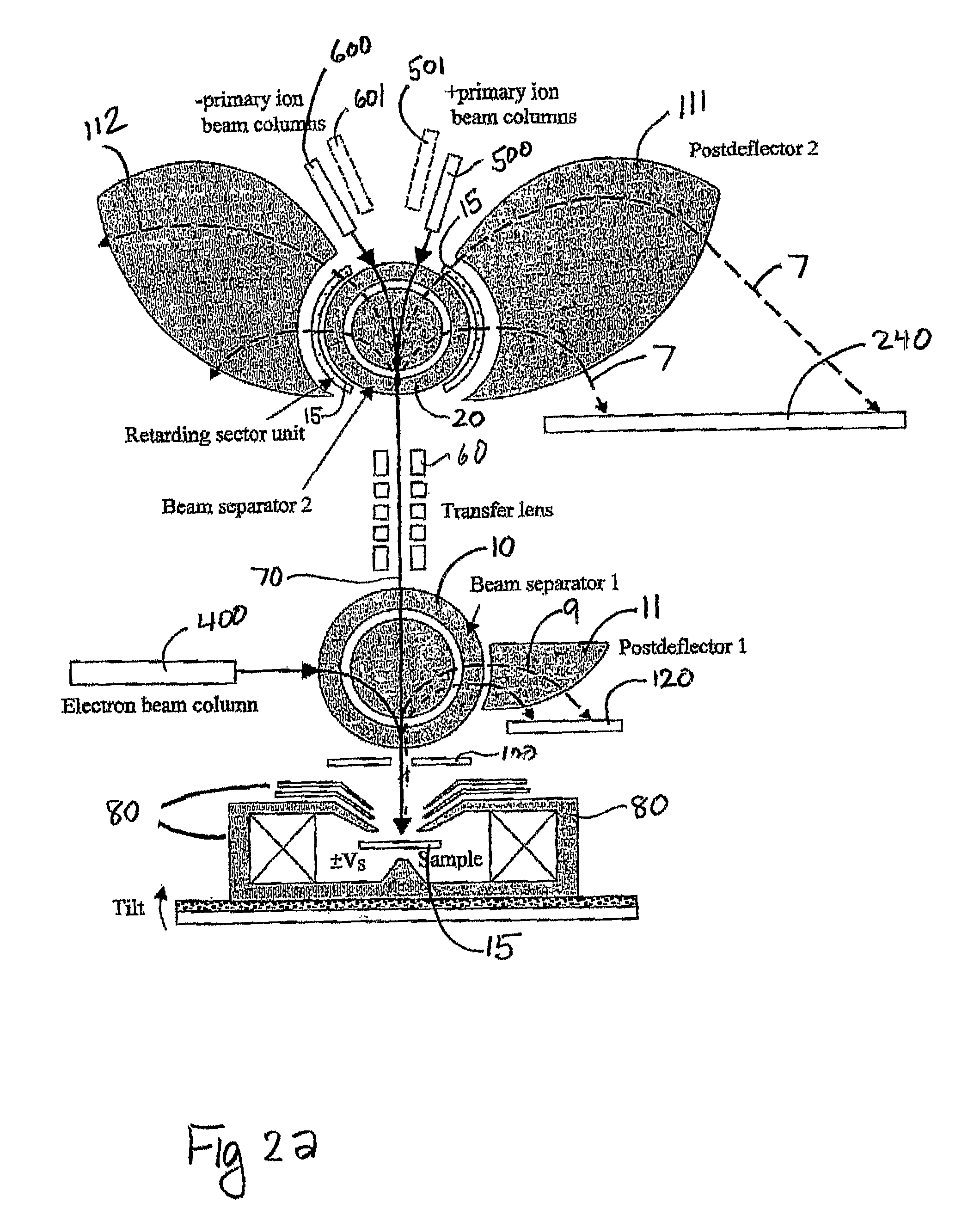
To minimize deflection aberrations, each charged particle primary beam (5), (4), needs to be pre-focused so that its incoming rays are directed towards the centre of the beam separator. A primary ion beam (5), as shown in FIG. 1, is first directed towards the centre of beam separator 2 (20). The ion beam undergoes a deflection (shown as a bend in the path (50)) before traveling into an electrostatic transfer lens (60), which provides suitable pre-focusing so that it converges towards the centre of beam separator 1 (10). Beam separator 1 (10) is designed to deflect an electron primary beam down on to the same optical axis (70) as the primary ion beam. There will be a very small tendency of beam separator 1 to deflect the primary ion beam also, but because it is designed to deflect electrons, this effect will be very small and can be compensated by suitably tilting the objective lens / specimen so that the primary ion beam strikes it perpendicularly (not indicated in FIG. 1, but shown schematically in FIG. 2a). After traversing beam separator 1, both the primary ion and electron beams are focused on to the specimen by a combined electrostatic / magnetic field objective lens (80). A second embodiment of the present invention, described in FIG. 2b, will disclose a mechanism for eliminating the necessity of tilting the sample. Specimen.
The objective lens can be designed to focus the scattered secondary ions / electrons (90) from the sample surface to a point around the centre of beam separator 1, without greatly affecting the primary ion / electron beam optics. An aperture (100) placed at the top of the objective lens is used to limit the energy and angular spread of transmitted secondary ions. The scattered electrons (90) are subsequently dispersed by beam separator 1, and their energy spectrum can be captured in parallel by a multi-channel electron detector (120). The transfer lens (60) can be designed to direct. scattered ions towards the centre of beam separator 2 (20), without greatly affecting the primary ion beam, so that they will be dispersed, according to their energies and charge-to-mass ratios. Beam separator 2, therefore, forms the first stage of a highly dispersive mass spectrometer.

Problems solved by technology

Although such an instruments can provide in situ SEM monitoring of FIB changes to a sample's surface or elemental identification, its spatial resolution is compromised by the fact that it uses a separate objective lens for each column, making it difficult to attain short working distances.

Method used


Image

  • Multi-beam ion/electron spectra-microscope
  • Multi-beam ion/electron spectra-microscope
  • Multi-beam ion/electron spectra-microscope

Examples


Embodiment Construction

The present invention provides two embodiments of a multi-beam charged particle instrument that can simultaneously focus an electron beam and a variety of primary ion beams upon a material sample and can then analyze the energy / mass spectra of emitted electron and secondary ion species from the sample. In the following, we will describe the component elements of the instrument and indicate how they operate to fulfill the objects of the invention.

1. The Instrument

Referring now to FIG. 2a, there is shown the schematic of a first preferred embodiment of a dual electron / ion instrument that has a parallel (i.e., simultaneously operative) energy spectrometer for scattered electrons and a parallel mass spectrometer for secondary ions. The shaded area denotes parts of the instrument that are magnetic (contain magnetic fields to deflect moving charged particles). The SEM column (400), including e-gun, condenser lenses, scan unit, stigmator and aperture (not shown), directs an electron beam (...


PUM


Abstract

This invention is a multi-beam charged particle instrument that can simultaneously focus electrons and a variety of positive and negative ions, such as Gallium, Oxygen and Cesium ions, onto the same material target. In addition, the instrument has provision to simultaneously capture the spectrum of both secondary electrons and ions. The highly dispersive, high resolution mass spectrometer portion of the instrument is expected to detect and identify secondary ion species across the entire range of the periodic table, and also record a portion of their emitted energy spectrum. The electron energy spectrometer part of the instrument is designed to acquire the entire range of scattered electrons, from the low energy secondary electrons through to the elastic backscattered electrons.

Description

BACKGROUND OF THE INVENTION1. Field of the InventionThis invention relates to the use of a focused beam analytic instrument designed to obtain topographical, elemental and chemical information about a material sample by impinging deflected electron and ion beams upon that sample and interpreting the mass and energy spectra of resulting emissions from that sample.2. Description of the Related ArtAt present, Focused Ion Beam instruments (FIBs), Scanning Electron Microscopes (SEMs), Secondary Ion Mass Spectrometers (SIMS) and Auger Electron Spectrometers (AES) usually operate separately. Although each of these charged particle beam instruments has its own respective domain of usefulness, there are definite advantages to integrating them into one complete instrument. FIBs, most commonly used to make connections, repairs, milling and cross-sectioning of materials on the nano-scale, can benefit from the high imaging resolution capability that SEMs provide in order to closely monitor chang...

Claims


Application Information

Patent Timeline
Patent Type & Authority Patents(United States)
IPC IPC(8): H01J37/26H01J37/153
CPCH01J37/05H01J37/15H01J37/256H01J37/28H01J49/142H01J2237/31749H01J2237/0245H01J2237/057H01J2237/0825H01J2237/2527
Inventor KHURSHEED, ANJAM
Owner NAT UNIV OF SINGAPORE
Why Eureka
Try Eureka