Method and apparatus for calibrating an image capturing device, and a method and apparatus for outputting image frames from sequentially captured image frames with compensation for image capture device offset

a technology of image capture device and output device, which is applied in image data processing, television systems, traffic control systems, etc., can solve the problems of inability to accurately position objects in respective plan view images of the ground relative to vehicles, inability to operate motor vehicles in generally relatively harsh environments, etc., and achieves automatic calibration, the effect of easy and frequent calibration and convenient production

Active Publication Date: 2011-05-24
CONNAUGHT ELECTRONICS
View PDF3 Cites 99 Cited by
  • Summary
  • Abstract
  • Description
  • Claims
  • Application Information

AI Technical Summary

Benefits of technology

[0106]The advantages of the invention are many. A particularly important advantage of the invention is that it provides relatively accurate calibration of the output of an image capture device without the need for special calibration grids and the like. This has the particularly important advantage that there is no need to accurately align the vehicle with a calibration grid or other external calibration devices or patterns.
[0107]Where the image capture device is mounted on a side mirror housing of the vehicle, and the side mirror housing is of the type which is swivelable from an operative position with the rear view mirror directed substantially rearwardly of the vehicle and a rest position extending substantially along and adjacent the vehicle, while the side rear view mirror housing is being swivelled from the rest position to the operative position, the output of the image capture device can be automatically calibrated. Since side mirror housings of such vehicles, in general, are swivelled from the rest to the operative position each time the ignition of a vehicle is activated, the output of the image capture device or devices are calibrated each time the ignition of the vehicle is activated if the calibration system is activated in response to activation of the ignition.
[0108]Where an image capture device is fixedly mounted on a vehicle, calibration can also be periodically carried out by merely putting the calibration system into a calibration mode.
[0109]Additionally, by virtue of the fact that calibration of the output of the image capture device or devices can be readily easily and frequently carried out, images outputted for display on a visual display screen can be readily easily produced with compensation for offset of the image capture device or devices from an ideal position. For example, where image capture devices are mounted to the sides of the vehicle with the field of view of the image capture devices directed downwardly in order to capture plan view images of the ground on respective opposite adjacent the side of the vehicle, after calibration by the method according to the invention, subsequent plan view images of the ground can be produced corrected for offset of the image capture device using calibration values derived during calibration, which are accurate representations of top plan views of the ground on respective opposite sides of the vehicle for display with a plan view image of the vehicle.
[0110]By producing the offset correction transformation function for each image capture device during calibration of the output of the image capture device, an offset correction look-up table can readily easily be produced from the offset correction transformation function, and the offset correction look-up table can indicate the locations at which at least some of the pixels of the captured image frame should be placed in a reconstructed image frame with compensation for offset of the image capture device from an ideal position thereof, for outputting to a visual display unit. A particularly important advantage of the invention is provided by producing the transformation function as a polynomial expression, and in particular, a polynomial expression of the second order or greater, since a polynomial expression is an efficient way of expressing and calculating a function, and the function can be made more or less accurate by adding or omitting terms, as the case may be.

Problems solved by technology

Otherwise, the positions of objects in the respective plan view images of the ground will not be accurately positioned relative to the vehicle.
Conversely, if one of the image capture devices is mounted on a side mirror housing so that an image of a portion of the ground beneath a side of the vehicle is captured, the positions of objects captured in the plan view image will appear farther away from the vehicle than they actually are, with disastrous results, particularly if a driver is parking the vehicle parallel to a wall or bollards.
In practice this is not possible.
However, the environments in which motor vehicles must operate are generally relatively harsh environments, in that side mirror housings are vulnerable to impacts with other vehicles or stationary objects.
While such impacts may not render the orientation of the side mirror housing unsuitable for producing an adequate rear view from a rear view mirror mounted therein, such impacts can and in general do result in the image capturing device mounted therein being knocked out of alignment, in other words, being offset from its ideal position.
Such re-calibration, which typically would be carried out using a grid pattern on the ground, is unsatisfactory, since in general, it is impossible to accurately align the vehicle with the grid pattern in order to adequately calibrate the image capture device, unless the calibration is being carried out under factory conditions.

Method used


Image

  • Method and apparatus for calibrating an image capturing device, and a method and apparatus for outputting image frames from sequentially captured image frames with compensation for image capture device offset
  • Method and apparatus for calibrating an image capturing device, and a method and apparatus for outputting image frames from sequentially captured image frames with compensation for image capture device offset
  • Method and apparatus for calibrating an image capturing device, and a method and apparatus for outputting image frames from sequentially captured image frames with compensation for image capture device offset

Examples


Embodiment Construction

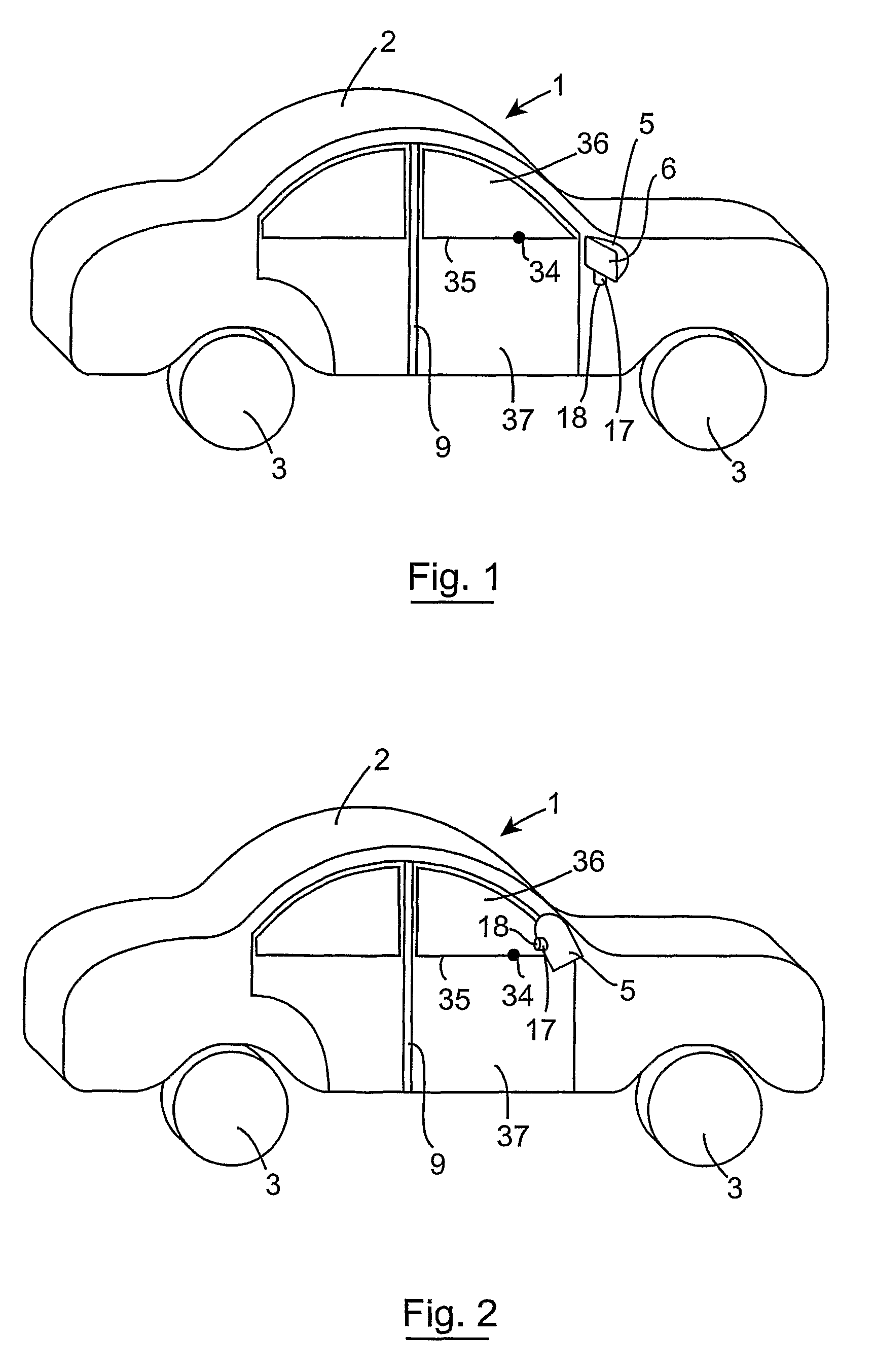
[0121]Referring to the drawings and initially to FIGS. 1 and 2, there is illustrated a motor vehicle according to the invention, indicated generally by the reference numeral 1, which in this embodiment of the invention is a motor car, although needless to say, it will be appreciated that the motor vehicle may be any motor vehicle, for example, a van, a truck, a lorry, a bus or any other such vehicle. The motor vehicle 1 comprises a body 2 supported on four ground engaging wheels 3. Two side mirror housings 5 are provided on the motor vehicle 1, one side rear view mirror housing 5 extending from each side of the body 2 of the motor vehicle 1. A rear view mirror 6 is housed within each side mirror housing 5, and in this embodiment of the invention each side mirror housing 5 is swivelably mounted on the body 2 and is swivelable from an operative position illustrated in FIG. 1 with the side mirror housing 5 extending sidewardly outwardly of the vehicle and the rear view mirror 6 facing ...


PUM


Abstract

A camera (17) mounted on a rear view minor housing (5) of a vehicle (1), which captures a plan view image of the ground on one side of the vehicle for display on an in-vehicle visual display unit (13) is calibrated to correct for offset of the camera (17) from an ideal position. During calibration an image of a reference point (34) on the vehicle (1) is captured as the mirror housing (5) is swiveled from a rest position to an operative position. The offset of the actual position of the image of the reference point in the captured image from its ideal position is computed, and a look-up table is prepared, which indicates the position at which pixels of subsequently captured image frames should be located to produce image frames with offset correction.

Description

FIELD OF THE INVENTION[0001]The present invention relates to a method and a calibration system for calibrating an output of an image capture device, of the type typically mounted on a motor vehicle to compensate for offset of the image capture device from an ideal position. The invention also relates to a method and an image vision system for producing an output image frame from a captured image frame captured by an image capture device with the output image frame with compensation for offset of the image capture device from an ideal position. The invention also relates to a vehicle comprising a calibration system for calibrating an output of an image capture device mounted on the vehicle to compensate for offset of the image capture device from an ideal position, and the invention further relates to a vehicle comprising an image capture device mounted thereon and an associated image vision system for producing an output image frame from a captured image frame captured by the image ...

Claims


Application Information

Patent Timeline
Patent Type & Authority Patents(United States)
IPC IPC(8): G06F19/00G06K9/36H04N5/228
CPCG06T2207/30204G06T2207/30252G06T7/80
Inventor DENNY, PATRICK EOGHANRAAB, TYCHO LORENZ ROLANDSHARMAN, LLOYD ANTHONY
Owner CONNAUGHT ELECTRONICS
Why Eureka
Try Eureka