Tapered roller bearing

a technology of tapered roller bearings and roller bearings, which is applied in the direction of bearing cooling, mechanical equipment, rotary machine parts, etc., can solve the problems of low-torque design, torque loss, and seizure of ribs, so as to reduce the amount of lubricating oil, and reduce the friction loss of bearings

Inactive Publication Date: 2011-05-31
JTEKT CORP
View PDF22 Cites 17 Cited by
  • Summary
  • Abstract
  • Description
  • Claims
  • Application Information

AI Technical Summary

Benefits of technology

[0015]With the above problems in view, it is an object of this invention to provide a tapered roller bearing in which lubricating oil can be efficiently supplied to an area of contact between a large end surface of each tapered roller and a roller guide surface of a rib of an inner ring, and a low-torque design and an anti-seizure property can be enhanced.
[0016]Another object of this invention is to provide a tapered roller bearing device in which even when the amount of lubricating oil within a tapered roller bearing is much reduced, seizure of a rib of an inner ring is less liable to occur, thereby achieving both of a low-torque design and seizure resistance.

Problems solved by technology

Particularly when the amount of supply of the lubricating oil is reduced in order to achieve a low-torque design of the tapered roller bearing so as to reduce a torque loss of a machinery, the amount of the lubricating oil supplied to the area of contact between the large end surface 232 of each tapered roller 230 and the roller guide surface 213 of the rib 212 of the inner ring 210 is liable to become insufficient, and this leads to a fear that seizure may occur.
Furthermore, in the tapered roller bearing disclosed in JP-A-01-193411, the lubricating oil resides within the bearing when the lip of the second seal is held in a closed condition, and an oil agitation loss is increased by this residing lubricating oil, so that a torque loss develops, and therefore the low-torque design can not be achieved.
However, during high-speed rotation, most of the lubricating oil flows toward an outer ring under the influence of a centrifugal force, and therefore the lubricating oil is not sufficiently distributed to the vicinity of the rib of the inner ring, and much heat is generated at an area of sliding contact between the rib of the inner ring and a large end surface of each tapered roller, and besides the generated heat can not be easily removed (that is, a temperature rise is liable to occur at localized areas), so that seizure is liable to develop.
On the other hand, in a pinion shaft support apparatus of a vehicle, etc., to reduce a running torque of a tapered roller bearing in order to achieve a low-loss design has been a global problem.
However, when the amount of the lubricating oil is reduced, the risk of seizure of the rib increases, and therefore at present, a large amount of lubricating oil is supplied to the tapered roller bearing.

Method used


Image

  • Tapered roller bearing
  • Tapered roller bearing
  • Tapered roller bearing

Examples


first embodiment

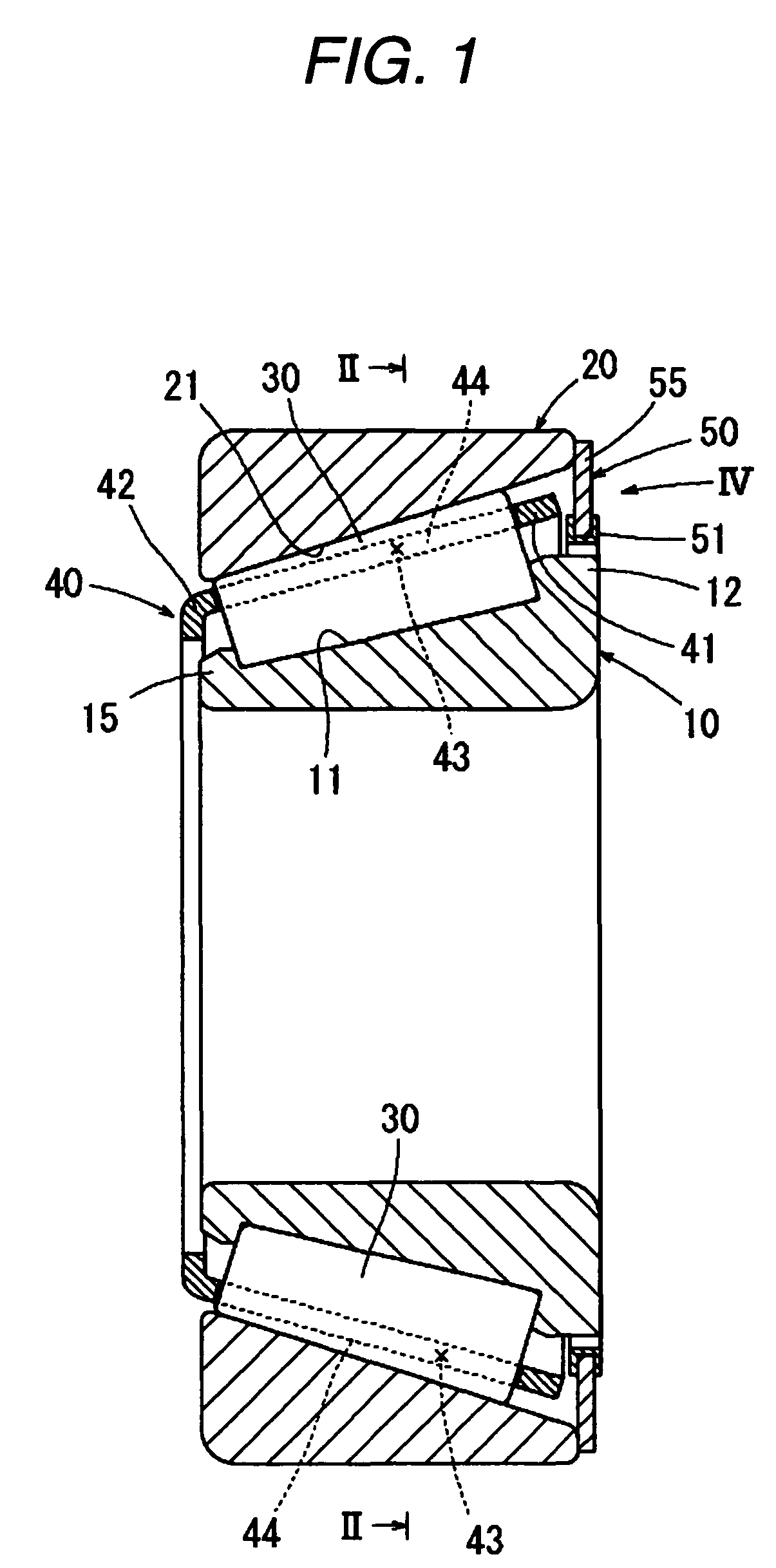
[0096]A first embodiment of the present invention will now be described with reference to FIGS. 1 to 5.

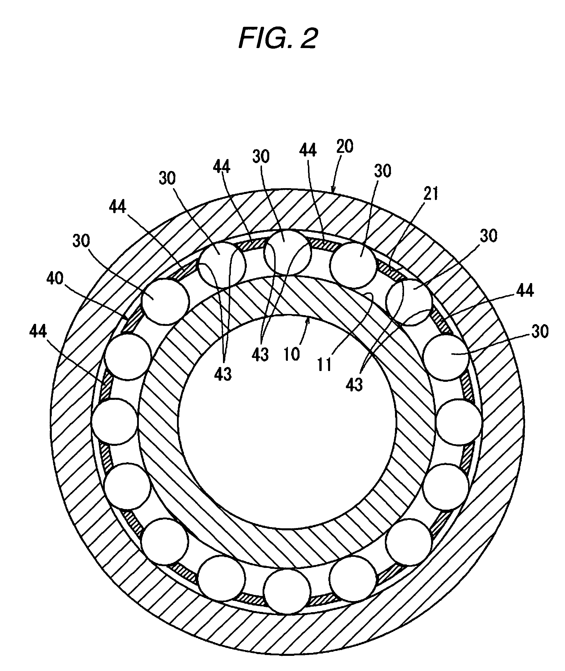
[0097]FIG. 1 is a longitudinal cross-sectional view showing the first embodiment of a tapered roller bearing of the invention. FIG. 2 is a transverse cross-sectional view taken along the line II-II of FIG. 1. FIG. 3 is a longitudinal cross-sectional view taken along the line III-III of FIG. 4, showing a closed condition of a closing element of an oil guide member on an enlarged scale. FIG. 4 is a rear view as seen in a direction of arrow IV of FIG. 1, showing a condition in which the oil guide member is mounted on an outer peripheral surface of a rib of an inner ring. FIG. 5 is an explanatory view showing a condition in which the closing element of the oil guide member is elastically deformed by a fluid pressure of lubricating oil, and is opened.

[0098]As shown in FIGS. 1 and 2, the tapered roller bearing comprises the inner ring 10, an outer ring 20, a plurality of tapered rollers ...

second embodiment

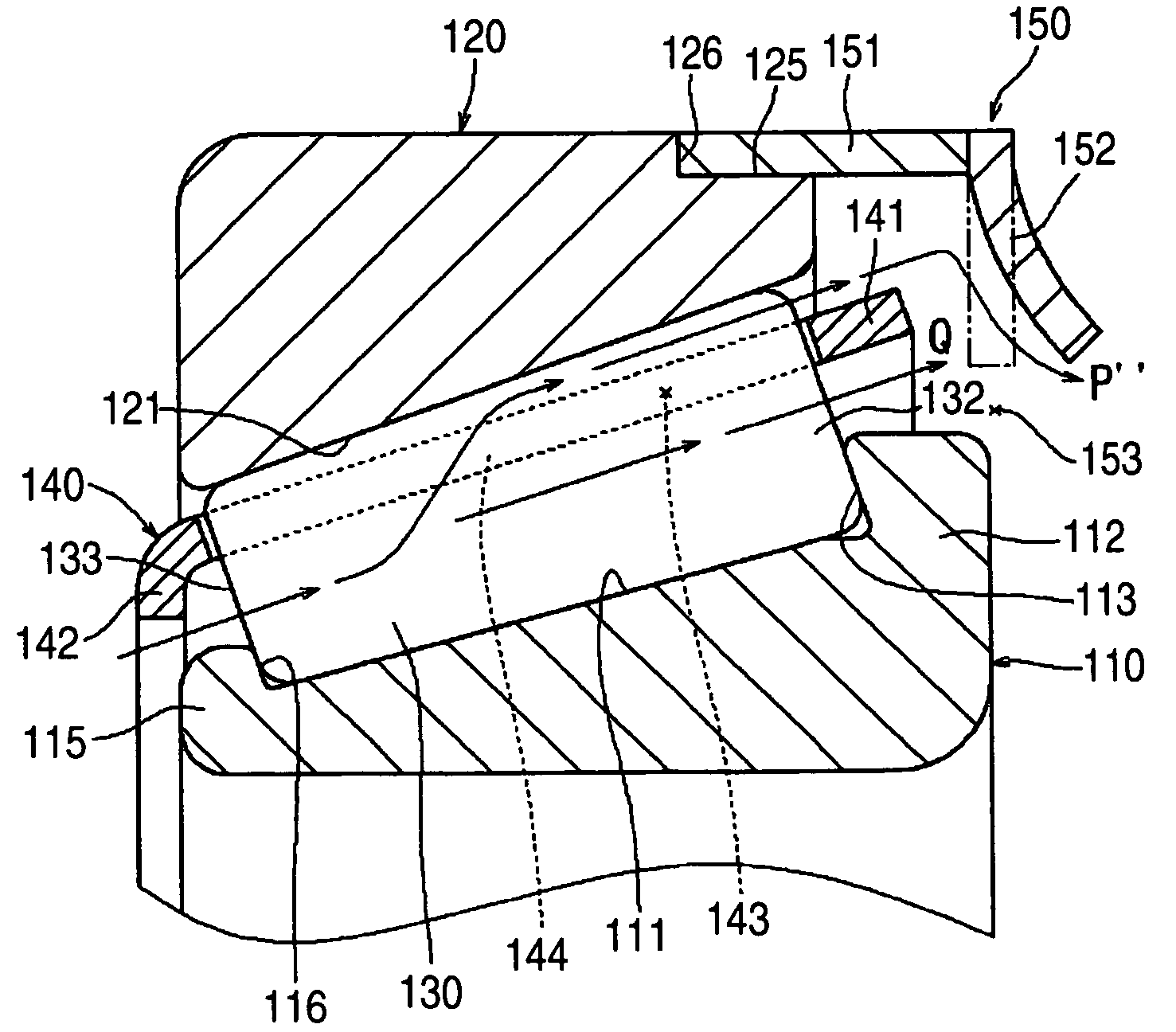
[0126]A second embodiment of the present invention will now be described with reference to FIGS. 6 to 10.

[0127]FIG. 6 is a longitudinal cross-sectional view showing the second embodiment of a tapered roller bearing of the invention. FIG. 7 is a transverse cross-sectional view taken along the line II-II of FIG. 6. FIG. 8 is a cross-sectional view showing the mounting relationship of an inner ring, an outer ring, tapered rollers, a cage and an oil guide member. FIG. 9 is an explanatory view showing a flow of lubricating oil during the rotation of the bearing. FIG. 10 is an explanatory view showing a condition in which an annular element of the oil guide member is elastically deformed by a fluid pressure of the lubricating oil in a direction to expand a discharge port.

[0128]As shown in FIGS. 6 and 7, the tapered roller bearing comprises the inner ring 110, the outer ring 120, the plurality of tapered rollers 130, the cage 140, and the oil guide member 150.

[0129]The inner ring 110 has a...

third embodiment

[0157]A third embodiment of the present invention will now be described with reference to FIGS. 13 to 16.

[0158]FIG. 13 is a longitudinal cross-sectional view showing the third embodiment of a tapered roller bearing of the invention. FIG. 14 is a transverse cross-sectional view taken along the line II-II of FIG. 13. FIG. 15 is an explanatory view showing a flow of lubricating oil during the rotation of the bearing. FIG. 16 is an explanatory view showing a condition in which an annular oil guide member is moved away from an end surface of an outer ring into an open condition by a fluid pressure of lubricating oil during the rotation of the bearing.

[0159]As shown in FIG. 13, the tapered roller bearing comprises an inner ring 310, an outer ring 320, a plurality of tapered rollers 330, a cage 340, and the annular oil guide member 350.

[0160]The inner ring 310 has a tapered raceway surface 311 formed on an outer peripheral surface thereof, and a large rib 312 and a small rib 315 are formed...


PUM


Abstract

A tapered roller bearing includes: an oil guide member that opens and closes an annular opening between an outer peripheral surface of a large rib of an inner ring and an outer ring and is mounted on the large rib; and a discharge port that discharges, along the outer peripheral surface of the large rib, lubricating oil and is formed through an inner peripheral portion of the oil guide member. The oil guide member includes a closing portion for closing the annular opening. When a fluid pressure of the lubricating oil which flows through pockets of a cage toward an inner peripheral surface of the outer ring is below a predetermined values, the closing portion closes the annular opening and guides the lubricating oil toward the discharge port. When the fluid pressure exceeds the predetermined value, the closing portion opens the annular opening.

Description

BACKGROUND OF THE INVENTION[0001]This invention relates to a tapered roller bearing and more particularly to a tapered roller bearing device which supports a pinion shaft, for example, of a final reduction gear (differential gear) of an automobile, and is lubricated by lubricating oil received within the bearing device.[0002]In a conventional tapered roller bearing as shown in FIG. 23, a plurality of tapered rollers 230 are rollably disposed between a raceway surface 211 of an inner ring 210 and a raceway surface 221 of an outer ring 220 in such a manner that a large end surface 232 of each tapered roller 230 is slidingly guided by a roller guide surface 213 of a rib 212 of the inner ring 210 while a small end surface 233 of each tapered roller 230 is slidingly guided by a roller guide surface 216 of a small rib 215 of the inner ring 210. A cage 240 having pockets 243 respectively holding the tapered rollers 230 is disposed between the two raceway surfaces 211 and 221.[0003]There is...

Claims


Application Information

Patent Timeline
Patent Type & Authority Patents(United States)
IPC IPC(8): F16C33/66F16C33/58
CPCF16C19/364F16C33/6674F16C33/6685F16C33/7889F16C37/007F16C33/7813F16C2361/61F16C2240/40
Inventor SADA, TAKASHIMATSUYAMA, HIROKIHATTORI, TOMOYA
Owner JTEKT CORP
Why Eureka
Try Eureka