Cooling fan built into rotor

a cooling fan and rotor technology, applied in the direction of piston pumps, vessel construction, marine propulsion, etc., can solve the problems of limiting the performance of the motor, affecting the winding range, and generating heat, so as to improve the winding range, improve the motor performance, and improve the effect of the motor performan

Inactive Publication Date: 2011-05-31
MABUCHI MOTOR
View PDF15 Cites 20 Cited by
  • Summary
  • Abstract
  • Description
  • Claims
  • Application Information

AI Technical Summary

Benefits of technology

[0010]An object of the present invention is to solve the above-mentioned problems and to prevent interference between windings of a rotor and a cooling fan even when a large amount of wire is wound around the rotor so as to improve the performance of the motor, and enables attachment of the cooling fan to an intended portion. Further, the present invention enables the wire to be wound to the limit, to thereby improve the performance of the motor.
[0013]According to the present invention, even when a larger amount of wire is wound around the rotor in order to improve the performance of the motor, the expanded windings and the cooling fan do not interfere with each other, so that the cooling fan can be attached to an intended position. Even when the wire is wound to a region where the fan ring is conventionally disposed, the cooling fan does not interfere with the resultant windings. Since the windable range increases, the performance of the motor can be improved.

Problems solved by technology

However, in a motor which generates a high output and a large torque, large current flows through windings of the rotor, and heat is generated, whereby electrical, mechanical, and magnetic malfunctions occur.
Since the conventional cooling fan restricts the range in which winding can be performed (hereinafter referred to as the “windable range”) as described above, the conventional fan has a problem of limiting the performance of the motor.
In such a case, if an attempt is made to attach the cooling fan to the end surface of the rotor core, the second fan ring of the cooling fan comes into contact with the expanded winding, so that attachment of the cooling fan to an intended position becomes impossible.
Interference (contact) of the cooling fan with the windings of the rotor causes a decrease in fan bonding strength and fixation of the fan to an improper position, which results in deterioration of rotor cooling performance, deterioration of mechanical balance of the rotor, and an increase in mechanical noise of the motor.
However, since the conventional cooling fan restricts the windable range, the motor performance is limited.
In order to allow attachment of the cooling fan, winding of the wire must be stopped before reaching the limit, so that the motor performance cannot be improved.

Method used


Image

  • Cooling fan built into rotor
  • Cooling fan built into rotor
  • Cooling fan built into rotor

Examples


Embodiment Construction

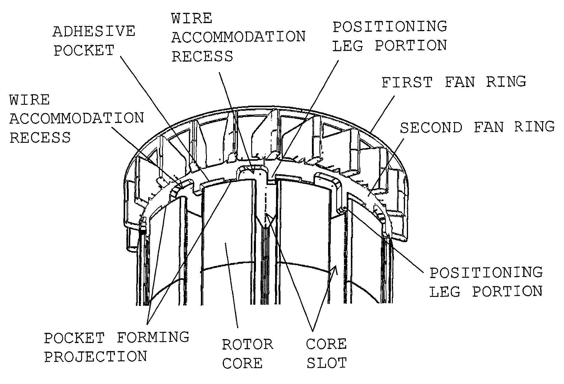
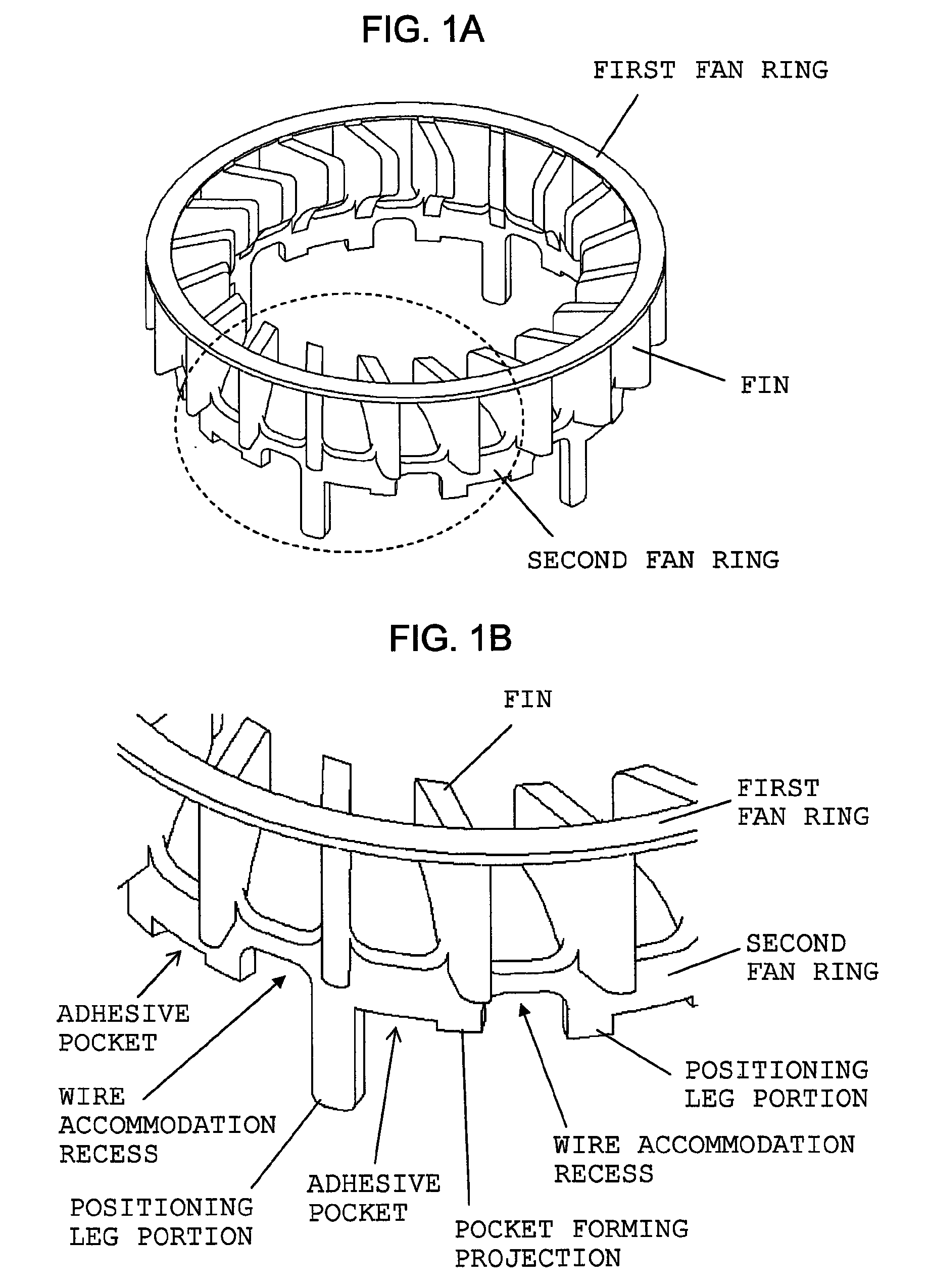
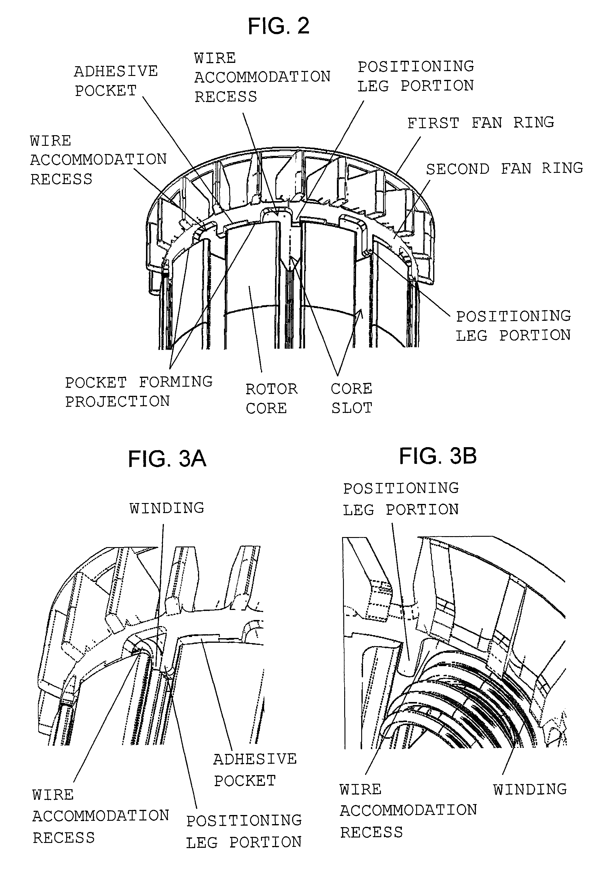
[0025]The present invention will now be described by way of examples. FIG. 1A is a perspective view showing a first example cooling fan configured in accordance with the present invention, and FIG. 1B is an enlarged view of a portion of FIG. 1A within a broken-line circle. The cooling fan is integrally formed of, for example, a synthetic resin such that a plurality of fins are disposed between and connected to first and second fan rings separated from each other along an axial direction. When the cooling fan is attached to the rotor, the first fan ring is located radially outward of an end portion of a commutator, so that a clearance is provided between the first fan ring and an outer circumferential surface of the commutator so as to allow air to flow through the clearance. The second fan ring has an end surface facing a thrust direction (parallel to the axial direction of a motor shaft), and the end surface is bonded to an end surface of a rotor core near the outer circumference t...


PUM


Abstract

A cooling fan includes a fan ring to be attached to an end surface of a rotor core near the outer circumference thereof, and a plurality of fins connected to the fan ring. The fan ring has positioning leg portions provided on an end surface thereof facing a thrust direction. The fan ring is positioned in relation to the rotor core through insertion of the positioning leg portions into core slots of the rotor core. The fan ring has wire accommodation recesses which are formed on the end surface of the fan ring facing the thrust direction and communicate with the core slots.

Description

BACKGROUND OF THE INVENTION[0001]1. Field of the Invention[0002]The present invention relates to a rotor-attachment cooling fan which is attached to the rotor of a motor for self cooling.[0003]2. Description of the Related Art[0004]Small-sized motors used for electric power tools must satisfy various requirements such as high output, large torque, compactness, light weight, low power consumption, and high cooling performance (for preventing temperature increase of a motor itself). In order to satisfy these requirements in a well-balanced manner, a thicker wire of an increased length must be wound around a rotor having a limited size. However, in a motor which generates a high output and a large torque, large current flows through windings of the rotor, and heat is generated, whereby electrical, mechanical, and magnetic malfunctions occur. In order to prevent these malfunctions, a cooling fan is attached to the rotor for self cooling. Further, it is known that, in the case where such...

Claims


Application Information

Patent Timeline
Patent Type & Authority Patents(United States)
IPC IPC(8): H02K9/06
CPCH02K9/06H02K3/12H02K23/30
Inventor KATO, MASAHIKOMIYAJIMA, YUSUKE
Owner MABUCHI MOTOR
Why Eureka
Try Eureka