Heating element incorporating an array of transistor micro-heaters for digital image marking

a transistor micro-heater and array technology, applied in the direction of electrographic process, recording apparatus, instruments, etc., can solve the problems of high cost, low total power requirement for addressing a large-area surface at reasonable high speed, and inefficient thermal print head

Inactive Publication Date: 2011-05-31
XEROX CORP
View PDF10 Cites 10 Cited by
  • Summary
  • Abstract
  • Description
  • Claims
  • Application Information

AI Technical Summary

Problems solved by technology

Also, the thermal print head is slow and energy inefficient.
The total power requirement for addressing a large-area surface at reasonably high speed, however, is extremely high compared to common high power laser systems.
The lack of an inexpensive, powerful laser and the complexity of optical systems make it nearly impossible to create a fast, compact, and cheap heat-based marking engine using current laser technology.

Method used


Image

  • Heating element incorporating an array of transistor micro-heaters for digital image marking
  • Heating element incorporating an array of transistor micro-heaters for digital image marking
  • Heating element incorporating an array of transistor micro-heaters for digital image marking

Examples


Embodiment Construction

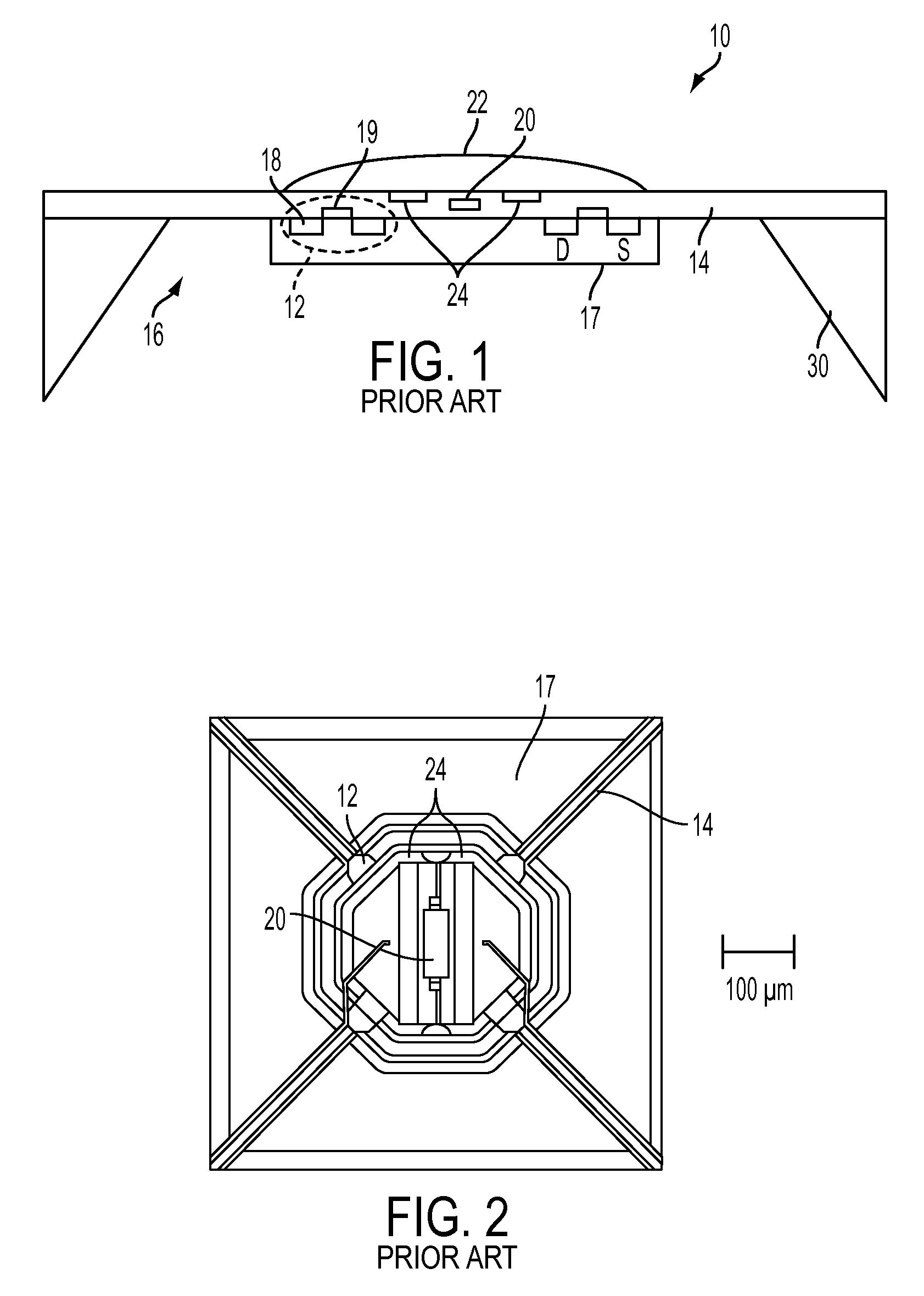
[0030]A schematic view of an example of a prior art micro-hotplate-based chemical sensor 10 with an integrated PMOS transistor heater 12 is shown in FIG. 1. In order to ensure a good thermal insulation, only the dielectric layers of the CMOS process form the membrane 14. The inner section 16 of the dielectric membrane 14 includes an n-well silicon island 17 (e.g., 300 μm base length) underneath the dielectric layers (e.g., 500×500 μm). The n-well 17 is electrically insulated and serves as heat spreader owing to the good thermal conductivity of silicon. It also hosts the pMOS transistor heating element 12, which includes p-diffusion 18 and a gate 19 (e.g., 5 μm gate length and 710 μm overall gate width). A special ring-shape transistor arrangement improves homogeneous heat distribution. A poly-silicon resistor 20 is used to measure the temperature on the micro-micro-heater 10. The resistance of the nanocrystalline SnO thick-film layer 22 is read out by means of two noble-metal-coated...


PUM


Abstract

The exemplary embodiments disclosed herein incorporate transistor heating technology to create micro-heater arrays as the digital heating element for various marking applications. The transistor heaters are typically fabricated either on a thin flexible substrate or on an amorphous silicon drum and embedded below the working surface. Matrix drive methods may be used to address each individual micro-heater and deliver heat to selected surface areas. Depending on different marking applications, the digital heating element may be used to selectively tune the wettability of thermo-sensitive coating, selectively change ink rheology, selectively remove liquid from the surface, selectively fuse / fix toner / ink on the paper.

Description

BACKGROUND[0001]The exemplary embodiments disclosed herein relate to heating elements incorporating arrays of transistor micro-heaters for printing and image marking applications.[0002]By way of background, current heat-based image marking engines incorporate either thermal print head or laser heating technology. The thermal print head must physically contact the surface in order to directly deliver heat to selected pixels, which restricts its application away from non-contact required environment, such as the nip region between two rollers. Also, the thermal print head is slow and energy inefficient. In the laser heating technology, optical energy is absorbed and converted to heat, providing an ideal non-contact heating mechanism. The total power requirement for addressing a large-area surface at reasonably high speed, however, is extremely high compared to common high power laser systems. The lack of an inexpensive, powerful laser and the complexity of optical systems make it near...

Claims


Application Information

Patent Timeline
Patent Type & Authority Patents(United States)
IPC IPC(8): G03G15/20B41J2/315
CPCB41M7/009G03G15/2014
Inventor ZHOU, JINGLAW, KOCK-YEE
Owner XEROX CORP
Why Eureka
Try Eureka