

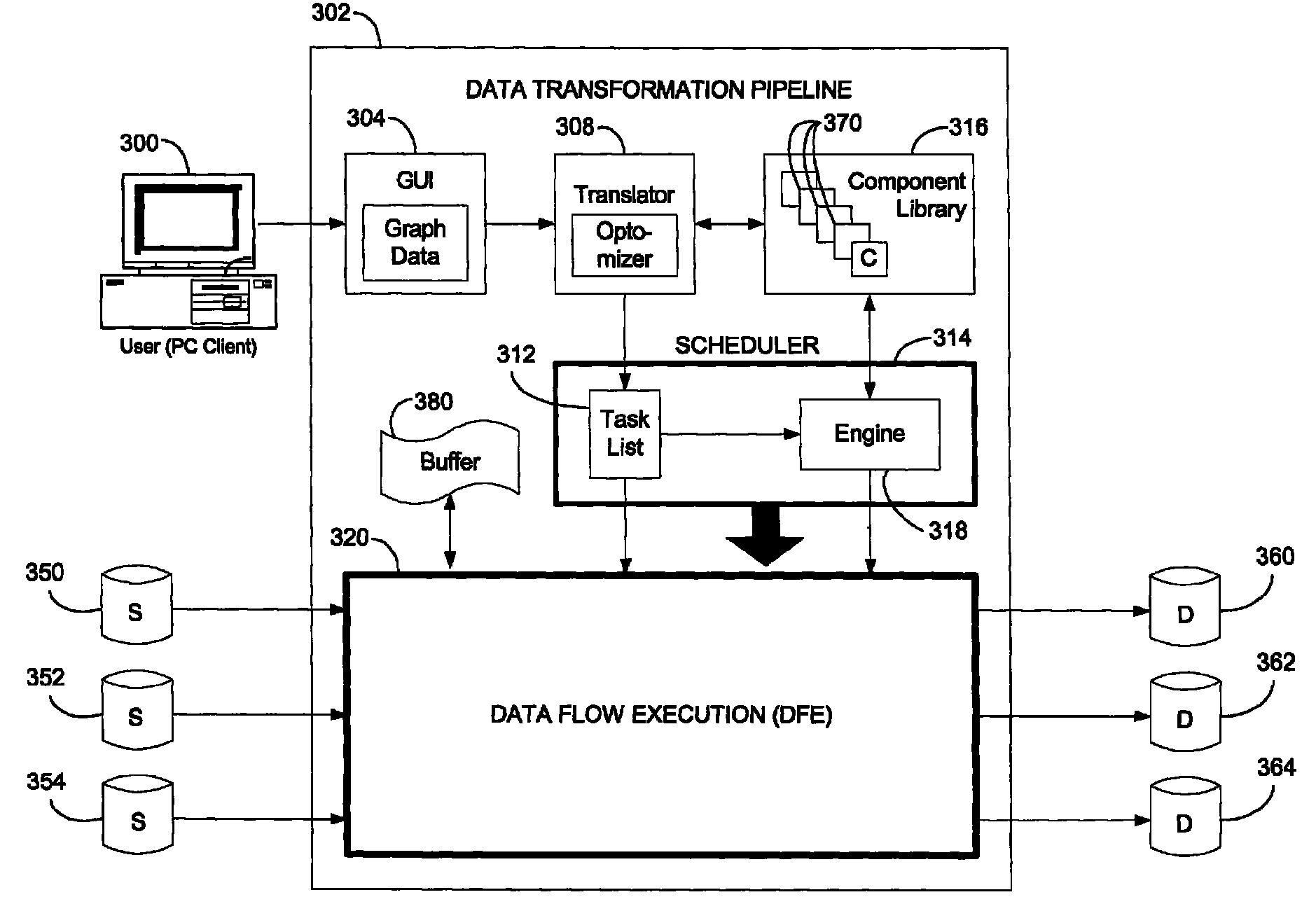
Systems and methods for scheduling data flow execution based on an arbitrary graph describing the desired data flow
- Summary
- Abstract
- Description
- Claims
- Application Information
AI Technical Summary
Benefits of technology
Problems solved by technology
Method used
Image

Examples
Embodiment Construction
Overview
[0033]The following discussion is directed to a system and method for scheduling data flow execution based on an arbitrary graph describing the desired flow of data from at least one source to at least one destination. The subject matter is described with specificity to meet statutory requirements. However, the description itself is not intended to limit the scope of this patent. Rather, the inventors have contemplated that the claimed subject matter might also be embodied in other ways, to include different elements or combinations of elements similar to the ones described in this document, in conjunction with other present or future technologies. Moreover, where the embodiments described herein describe the invention in connection with row-level access and processing, it should be noted that the invention is by no means limited to row-level access and processing and could be applied on a column basis or a table basis as well.
Computer Environment
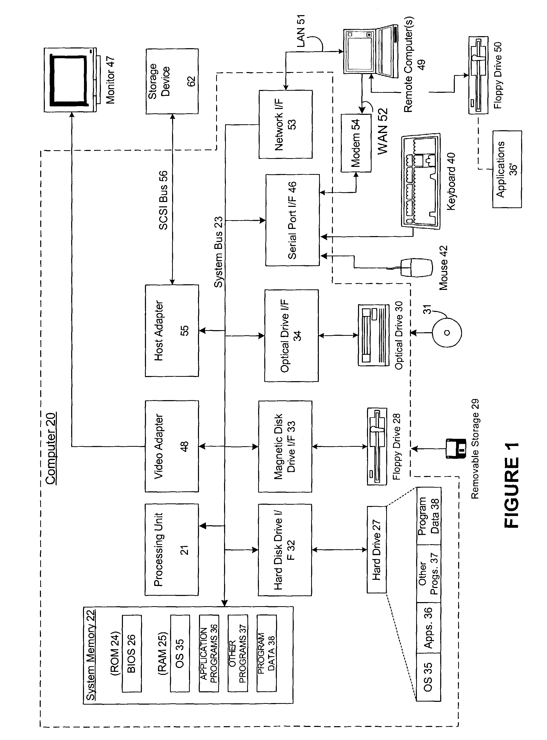
[0034]FIG. 1 and the followi...
PUM
 Abstract
Description
Claims
Application Information