Supercharge Your Innovation With Domain-Expert AI Agents!

Fiber optic sensors in MWD Applications

a fiber optic sensor and fiber optic technology, applied in the field of wellbore drilling systems, can solve the problems of limited or specialized use of alternative methods of telemetry, such as low frequency electromagnetic and acoustics, difficult and expensive maintenance, and special fabrication of pipe sections, etc., to reduce the complexity of data acquisition systems, improve the robustness, and simplify the design of the bottomhole assembly

Inactive Publication Date: 2011-06-07
BAKER HUGHES INC
View PDF45 Cites 53 Cited by
  • Summary
  • Abstract
  • Description
  • Claims
  • Application Information

AI Technical Summary

Benefits of technology

This approach enhances data transmission rates, simplifies the design of bottomhole assemblies, and allows for robust, high-resolution 3D measurements and control, addressing the limitations of conventional systems by providing a high-bandwidth data link and reducing complexity in data acquisition.

Problems solved by technology

Alternative methods of telemetry, such as low frequency electromagnetic and acoustics, have been investigated and found to be of limited or specialized use.
U.S. Pat. No. 4,095,865 to Denison, et al, describes sections of drill pipe, pre-wired with an electrical conductor, however each section of pipe is specially fabricated and difficult and expensive to maintain.
Acoustic systems suffer from attenuation and filtering effects caused by reflections at each drill joint connection.
Thus, to date, the only practical and commercial method of MWD telemetry is modulation of mud flow and pressure, which has a relatively slow data rate.
While conventional system utilizing fiber optics provide some additional functionality versus prior wellbore communication and measurement systems, advances in wellbore drilling technologies have to date outpaced the benefits provided by such conventional fiber optic arrangements.

Method used


Image

  • Fiber optic sensors in MWD Applications
  • Fiber optic sensors in MWD Applications
  • Fiber optic sensors in MWD Applications

Examples


Embodiment Construction

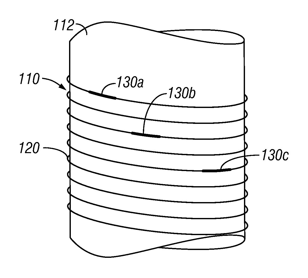
[0020]The present invention relates to devices and methods that measure parameters of interest utilizing fiber optic sensors and that provide data communication via optical fibers for wellbore drilling systems. The present invention is susceptible to embodiments of different forms. There are shown in the drawings, and herein will be described in detail, specific embodiments of the present invention with the understanding that the present disclosure is to be considered an exemplification of the principles of the invention, and is not intended to limit the invention to that illustrated and described herein.

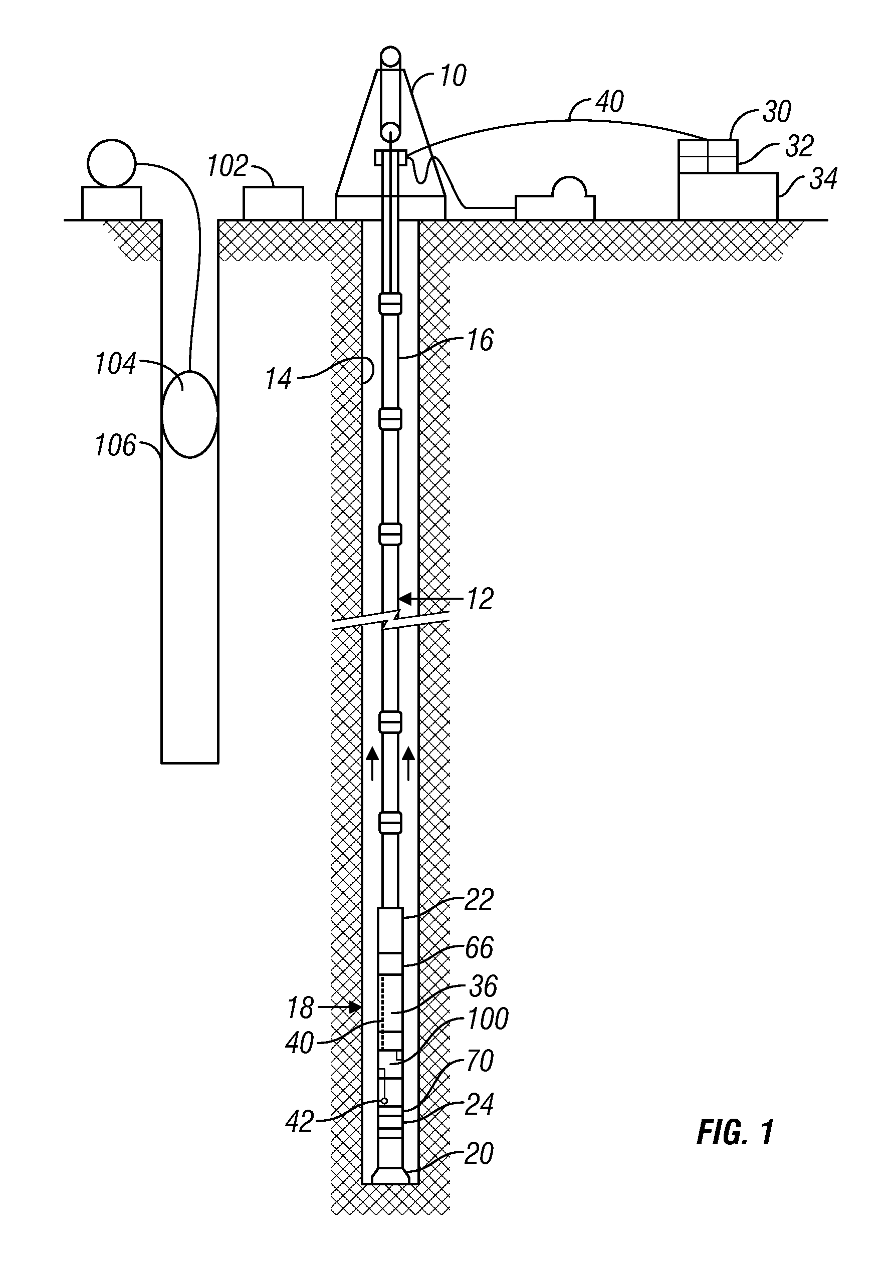
[0021]Referring initially to FIG. 1, there is shown as an example and not as a limitation, a drilling operation has a conventional derrick 10 for supporting a drill string 12 in a borehole 14, also called a wellbore. The drill string 12 includes multiple sections of drill pipe 16 connected together by threaded connections. In other embodiments, the drill string 12 can include other ...


PUM


Abstract

A wellbore drilling system utilizes optical fibers to measure parameters of interest and to communicate data. One or more electrical conductors are used to provide power to the components of the drilling system. The acquisition electronics for operating fiber optic sensors can be positioned at the surface and / or in the wellbore. In some embodiments, one optical fiber includes a plurality of sensors, each of which can measure the same or different parameters. A multiplexer multiplexes optical signals to operate such sensor configurations. Optical fiber sensors for acoustic measurements can include a cylindrical member wrapped by one or more optical fibers. The sensors can be configured as needed to provide a 3D representation of the pressure measurements.

Description

CROSS REFERENCE TO RELATED APPLICATIONS[0001]This application takes priority from U.S. Provisional Patent Application No. 60 / 844,791, filed Sep. 15, 2006.BACKGROUND OF THE INVENTION[0002]1. Field of the Invention[0003]This invention relates generally to wellbore drilling systems and other downhole devices that utilize fiber optics.[0004]2. Description of the Related Art[0005]The oilfield industry currently uses two extremes of communication within wellbores. The classification of these two extremes relate to the timing of the wellbore construction. On extreme may occur during the wellbore construction whereas the other extreme may occur after wellbore construction and during the production of hydrocarbons. During the drilling and completion phases, communication is accomplished using a form of mud pulse telemetry commonly utilized within measurement while drilling (MWD) systems. Alternative methods of telemetry, such as low frequency electromagnetic and acoustics, have been investig...

Claims


Application Information

Patent Timeline
Patent Type & Authority Patents(United States)
IPC IPC(8): E21B47/026
CPCE21B47/01E21B47/123E21B47/06E21B47/135
Inventor MATHISZIK, HOLGERCSUTAK, SEBASTIANKRUEGER, VOLKER
Owner BAKER HUGHES INC
Features
  • R&D
  • Intellectual Property
  • Life Sciences
  • Materials
  • Tech Scout
  • Unparalleled Data Quality
  • Higher Quality Content
  • 60% Fewer Hallucinations
Learn More