Fluid pressure booster

a technology of flue gas and booster, which is applied in the direction of braking system, servomotor, braking components, etc., can solve the problems of generating abnormal noise, affecting the ease of manufacturing improvement, and unavoidably complicated shape of the control valve body b>14/b>, so as to suppress the generation of abnormal noise and hinder the effect of improving manufacturing eas

Active Publication Date: 2011-06-07
BOSCH CORP
View PDF13 Cites 5 Cited by
  • Summary
  • Abstract
  • Description
  • Claims
  • Application Information

AI Technical Summary

Benefits of technology

[0021]It is an object of the invention to provide a fluid pressure booster that suppresses the generation of abnormal noise caused when operation starts and that does not hinder improvements in ease of manufacturing, regardless of whether operation is performed suddenly or slowly.
[0025]According to the fluid pressure booster of the invention with the above-described structure, the flow rate restricting means exists during the time until the input shaft moves up to the determined stroke, but ceases to exist when the input shaft has moved as far as the determined stroke or more. Accordingly, it is possible to control the flow rate restriction of the high fluid pressure fluid without providing a special valve like an atmosphere valve that performs control to deactivate the flow rate restricting function of the flow rate restricting means, as in the vacuum pressure booster of Patent Document 2 described above. As a result, regardless of whether operation is performed suddenly or slowly, it is possible to effectively suppress the generation of abnormal noise when operation starts.
[0026]In addition, since it is not necessary to provide a special valve as described above, it is possible to suppress generation of abnormal noise when operation starts without having to specially modify the known high pressure valve to give it a complicated shape. Accordingly, the known valve can be used, whereby ease of manufacturing can be improved. In addition, the timing of the shift from restriction of the fluid flow rate by the flow rate restricting means to releasing this flow rate restriction can be controlled easily. In particular, the annular projection is formed on the valve plunger that is easy to process, and the orifice of the flow rate restricting means is formed between the outer peripheral surface of the annular projection and the inner peripheral surface of the fluid flow hole of the control valve body. As a result, ease of manufacturing is improved still further.

Problems solved by technology

In addition, when the air escapes from the variable pressure chamber 8, an abnormal noise is generated.
As a result, the shape of the control valve body 14 is unavoidably complicated.
As a result, the shape of the control valve body 14 is more complicated and requires more processing steps, which in turn hinders improvements in ease of manufacturing.

Method used


Image

  • Fluid pressure booster
  • Fluid pressure booster
  • Fluid pressure booster

Examples


Embodiment Construction

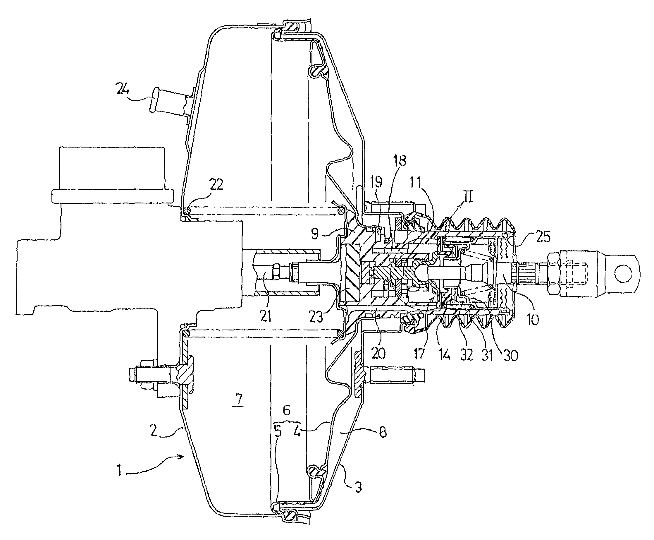
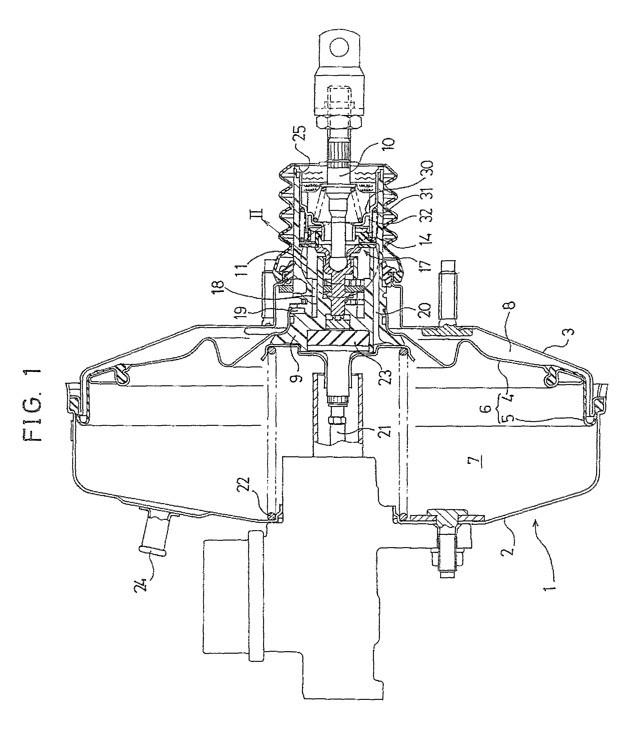
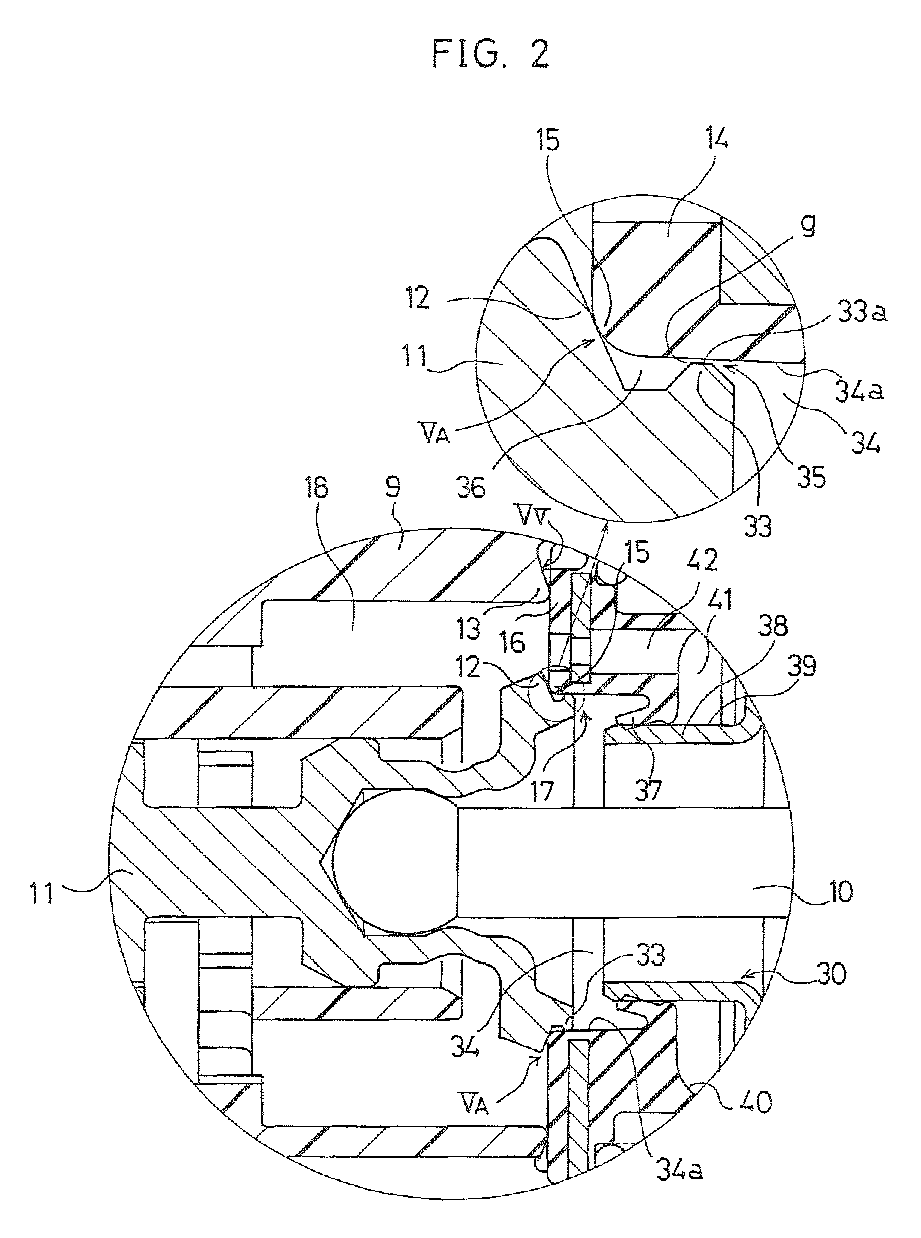
[0033]FIG. 1 shows a vacuum pressure booster of a brake system that is one applied example of an embodiment of a fluid pressure booster according to the invention. FIG. 2, which shows the same cross section as FIG. 4, is an expanded cross sectional view showing a section II shown in FIG. 1. Note that structural members that are the same as the known examples of vacuum pressure boosters shown in FIG. 4 and FIG. 5 are denoted with the same reference numerals, and a detailed explanation is omitted here.

[0034]In the control valve 17 in the known vacuum pressure booster 1 shown in FIG. 4 and described above, a rear end section of the control valve body 14 is fixed to the valve plunger 11 by a retainer 30, and the atmosphere valve 15 and the vacuum pressure valve 16 of the control valve body 14 are normally urged by a valve spring 31 to the atmosphere valve seat 12 and the vacuum pressure valve seat 13 sides. However, as shown in FIG. 1, in the control valve 17 of the vacuum pressure boos...


PUM


Abstract

In a fluid pressure booster, when an input shaft and a valve plunger advance, an atmosphere valve opens to introduce air into a variable pressure chamber. At this time, the input shaft has not moved by a predetermined stroke, and thus a projection of the valve plunger is positioned within an inner peripheral surface of a control valve body, thus forming an orifice, which causes air to be sucked at a restricted flow rate. As a result, generation of noise is suppressed. When the input shaft moves the predetermined stroke, the projection of the valve plunger is positioned away from the inner peripheral surface of the control valve body and the orifice is no longer formed. Accordingly, the flow rate of the air is not restricted by the orifice, and thus a relatively large amount of air is sucked into and introduced into the pressure variation chamber.

Description

CROSS-REFERENCE TO RELATED APPLICATION[0001]This application is a 35 USC 371 application of PCT / JP 2006 / 306986 filed on Mar. 27, 2006.BACKGROUND OF THE INVENTION[0002]1. Field of Invention[0003]The present invention relates to the technical field of fluid pressure boosters, exemplified for example by a vacuum pressure booster used in a brake booster or the like, that boost an input using a fluid pressure such as vacuum pressure or air pressure, etc. to generate a boosted output. More particularly, the invention relates to the technical field of fluid pressure boosters that suppresses the generation of abnormal noise caused by flow of fluid when operation starts.[0004]2. Description of the Prior Art[0005]In an automobile brake system, in order to allow a large braking force to be obtained using a small pedal depression force, conventionally, fluid pressure boosters of various types have been used that boost the pedal depression force using fluid pressure to generate a large output. O...

Claims


Application Information

Patent Timeline
Patent Type & Authority Patents(United States)
IPC IPC(8): B60T8/34
CPCB60T13/57
Inventor YAMASHITA, NOBUYUKI
Owner BOSCH CORP
Why Eureka
Try Eureka