High-frequency low-gain ring VCO for clock-data recovery in high-speed serial interface of a programmable logic device

Active Publication Date: 2011-06-07
ALTERA CORP
View PDF13 Cites 39 Cited by
  • Summary
  • Abstract
  • Description
  • Claims
  • Application Information

AI Technical Summary

Benefits of technology

[0023]FIG. 8 is a simplified block diagram of an illustrative system employing a programmable lo

Problems solved by technology

However, it is a common feature of most if not all high-speed serial data protocols that neither the clock nor information about the clock is

Method used


Image

  • High-frequency low-gain ring VCO for clock-data recovery in high-speed serial interface of a programmable logic device
  • High-frequency low-gain ring VCO for clock-data recovery in high-speed serial interface of a programmable logic device
  • High-frequency low-gain ring VCO for clock-data recovery in high-speed serial interface of a programmable logic device

Examples


Embodiment Construction

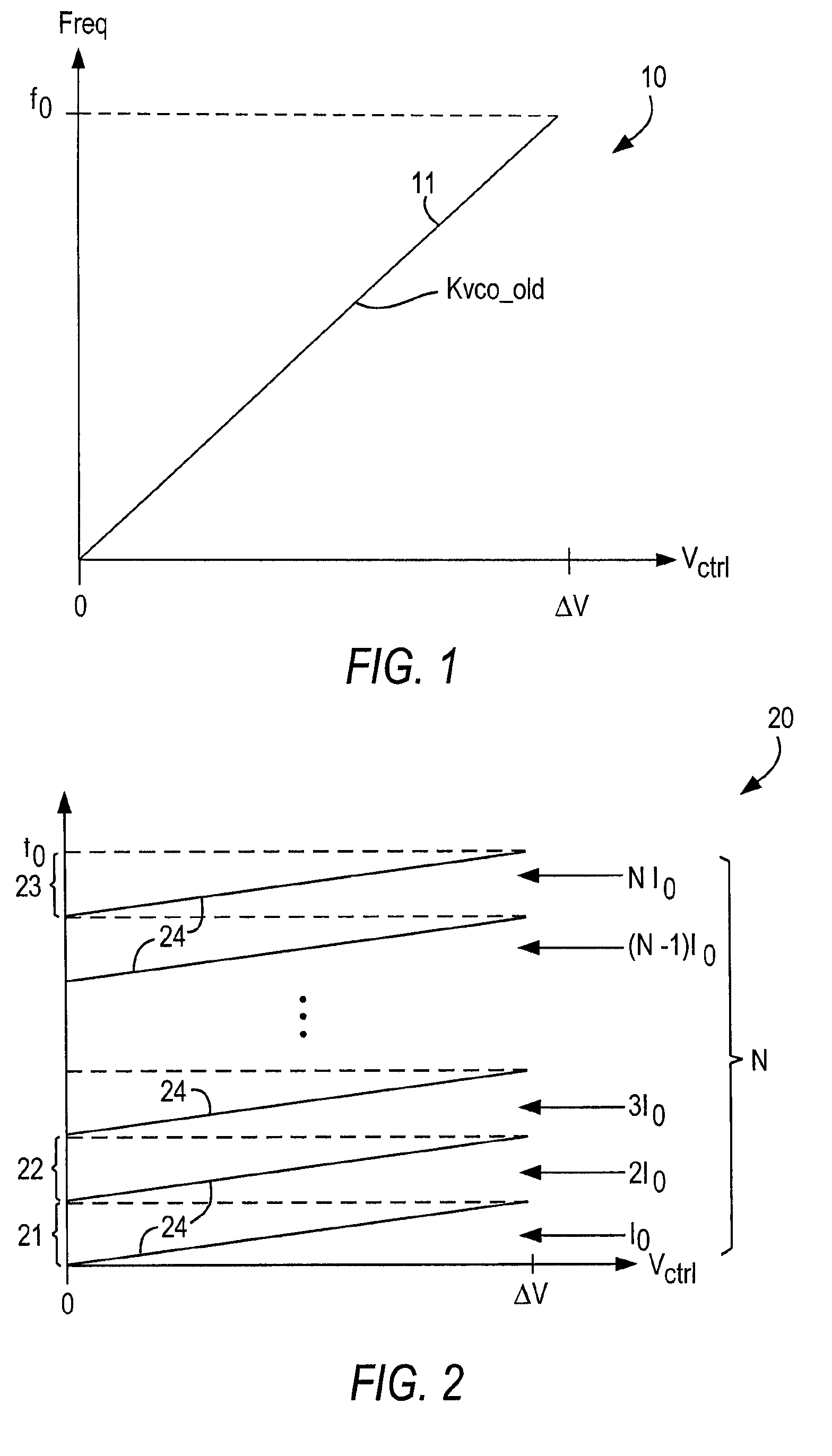
[0024]As described above, in the present invention the oscillator range preferably is broken into a plurality of frequency subranges. Within each subrange, the full range of the input control signal preferably covers only the subrange. Therefore, the frequency change per unit of input control signal—i.e., the gain—preferably is relatively low. To generate a particular oscillator output frequency, the correct frequency subrange preferably is selected first, and then the loop circuit feedback operates substantially conventionally to fine-tune the output signal. The “coarse tuning” of the frequency subrange may be achieved manually—i.e., by user input—or more preferably by an initial power-up calibration sequence.

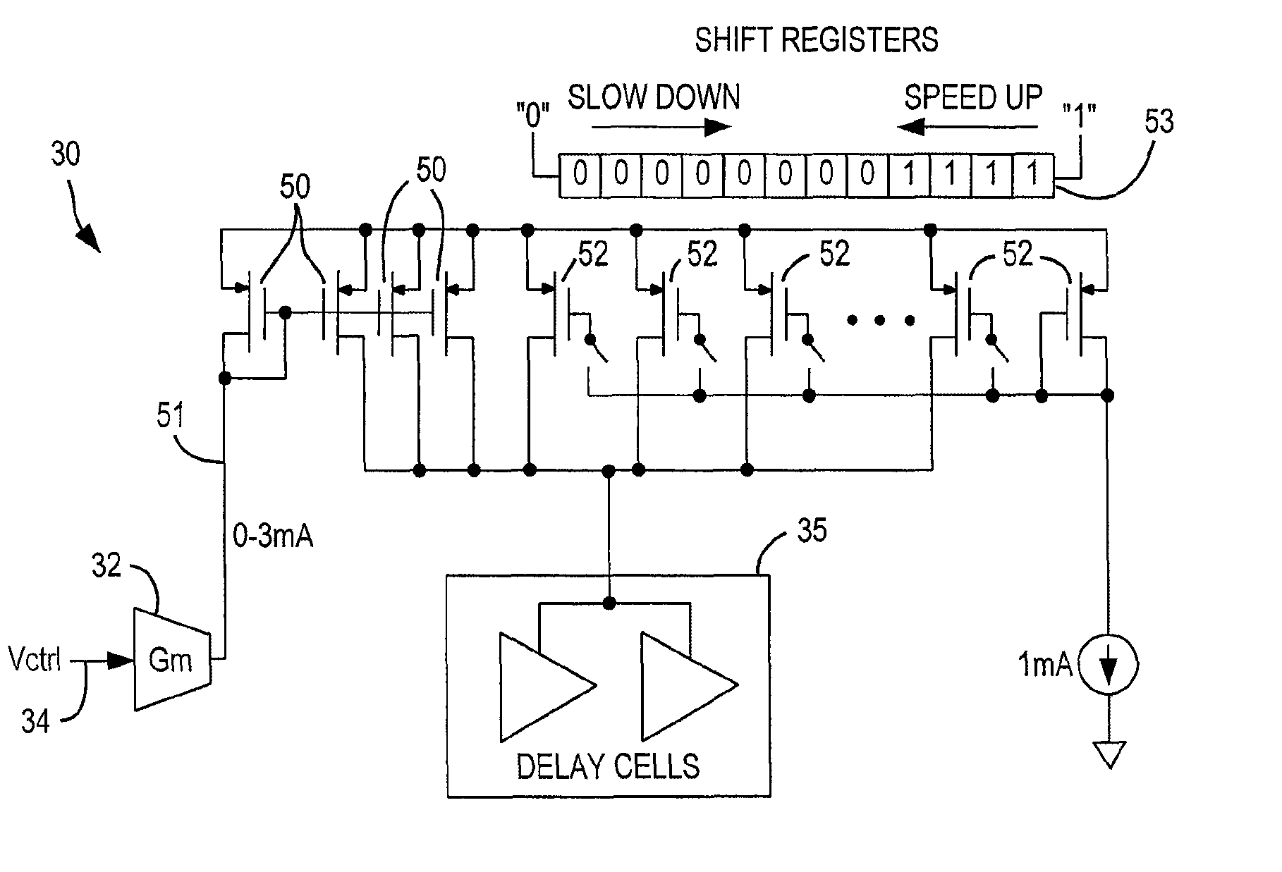
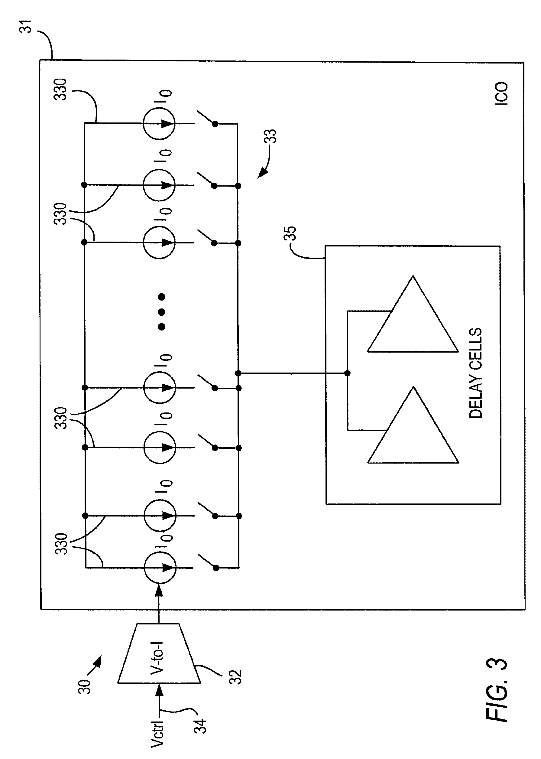
[0025]In a preferred embodiment, the oscillator is a current-controlled oscillator (ICO) rather than a voltage-controlled oscillator, as described above. Preferably, a current mirror structure, as described in more detail below, is used to select, or “coarse tune,” the frequen...


PUM


Abstract

A voltage-controlled oscillator operates at high frequency without high gain by dividing the frequency range into a plurality of subranges, which preferably are substantially equal in size. Within any subrange, the full extent of variation in the control signal changes the frequency only by the extent of the subrange. The gain is thus substantially equal to the gain one would expect for the full frequency range, divided by the number of subranges. The subrange may be selected manually, or by an initial calibration process. In one embodiment, the oscillator includes a voltage-to-current converter and a current-controlled oscillator, with a current mirror arrangement. In that embodiment, selection of the subrange may be controlled by turning on the correct number of current legs.

Description

CROSS REFERENCE TO RELATED APPLICATION[0001]This is a division of copending, commonly-assigned U.S. patent application Ser. No. 11 / 761,654, filed Jun. 12, 2007, which is hereby incorporated by reference herein in its entirety.BACKGROUND OF THE INVENTION[0002]This invention relates to a voltage-controlled oscillator (VCO) used as a frequency standard in clock-data recovery circuitry of a high-speed serial interface, especially in a programmable logic device (PLD).[0003]It has become common for PLDs to incorporate high-speed serial interfaces to accommodate high-speed (i.e., greater than 1 Gbps) serial input / output (I / O) standards. Many of these standards can operate at more than one clock rate. However, it is a common feature of most if not all high-speed serial data protocols that neither the clock nor information about the clock is sent with the data. Instead, the clock must be recovered from the data.[0004]For this purpose, it is known to use “clock-data recovery” techniques in hi...

Claims


Application Information

Patent Timeline
IPC IPC(8): H03B5/12
CPCH03K3/0322
Inventor DING, WEIQILIU, MENGCHI
Owner ALTERA CORP
Why Eureka
Try Eureka