Method, system, and apparatus for neural localization

a neural localization and neural technology, applied in the field of neural localization methods, systems and apparatuses, can solve the problems of risky nerve tissue damage, limited surgical procedure accuracy, and relatively inconvenient system selection

Active Publication Date: 2011-06-14
MIS IP HLDG LLC +1
View PDF676 Cites 106 Cited by
  • Summary
  • Abstract
  • Description
  • Claims
  • Application Information

AI Technical Summary

Benefits of technology

[0025]As mentioned, the plurality of anodes may be in electrical communication with a first anodal conductor, and the plurality of cathodes may be in electrical communication with a first cathodal conductor. In this variation, bipole pairs (formed by an anode and cathode) are arranged adjacent to each other so that they can form a substantially continuous broadcast field (e.g., bipole filed). Thus, adjacent bipole pairs share either a cathode or an anode, and an anode may communicate electrically with one or more adjacent cathode, and a cathode may communicate with one or more adjacent anodes. This arrangement allows a single network (in some cases formed by a single cathodal conductor and a single anodal conductor) to span a larger region of the surface using a relatively small exposed electrode area. As described below, there may also be advantages in the ability to detect adjacent nerves based on the multiple field orientations.
[0038]The device may also include a controller configured to control the scanning of the bipolar electrode pair. In some variations the devices also include a driver for driving the motion of the scanning surface. The driver may be a motor or other moving mechanism that drives the movement of the bipole pair. The device may also include an output for indicating which circumferential region the bipolar electrode pair corresponds to. For example, as the bipole pair is rotated, the output may indicate where around the circumference of the elongate body the bipole pair is positioned. This may help coordinate the location of the nerve relative to the probe.

Problems solved by technology

Many types of surgical intervention require manipulation of one or more medical devices in close proximity to a nerve or nerves, and therefore risk damage to the nerve tissue.
Although systems for monitoring neural tissue have been described, these systems are relatively imprecise.
Further, many of these systems require large current densities (which may also damage tissue) and may be severely limited in their ability to accurately guide surgical procedures.
Because the conductance of biological tissue may vary between individuals, over time in the same individual, and within different tissue regions of the same individual, it has been particularly difficult to predictably regulate the applied current.
Furthermore, the broadcast fields generated by such systems are typically limited in their ability to spatially resolve nerve location and / or orientation with respect to the medical device.
erves. Although multiple electrodes may be used to stimulate the tissue, the devices, systems and methods described are do not substantially control the broadcast
field. Thus, these systems may be limited by the amount of current applied, and the region over which they can detect

Method used


Image

  • Method, system, and apparatus for neural localization
  • Method, system, and apparatus for neural localization
  • Method, system, and apparatus for neural localization

Examples


example 1

Neural Localization When Treating Spinal Stenosis

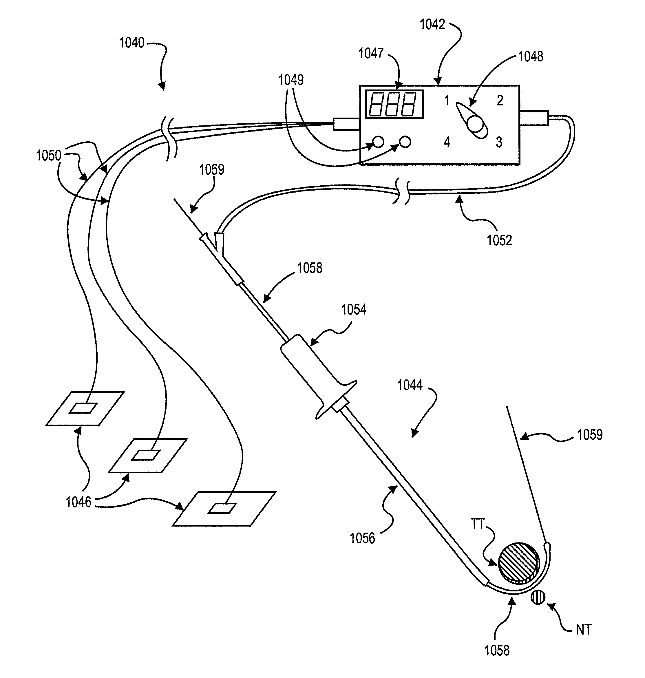
[0166]One area of surgery which could benefit from the development of less invasive techniques including neural localization is the treatment of spinal stenosis. Spinal stenosis often occurs when nerve tissue and / or blood vessels supplying nerve tissue in the lower (or “lumbar”) spine become impinged by one or more structures pressing against them, causing pain, numbness and / or loss of function in the lower back and / or lower limb(s). In many cases, tissues such as ligamentum flavum, hypertrophied facet joint and bulging intervertebral disc impinge a nerve root as it passes from the cauda equine (the bundle of nerves that extends from the base of the spinal cord) through an intervertebral foramen (one of the side-facing channels between adjacent vertebrae). Here we provide one example of a device for determining if a nerve is nearby that may be used as part of method for treating spinal stenosis.

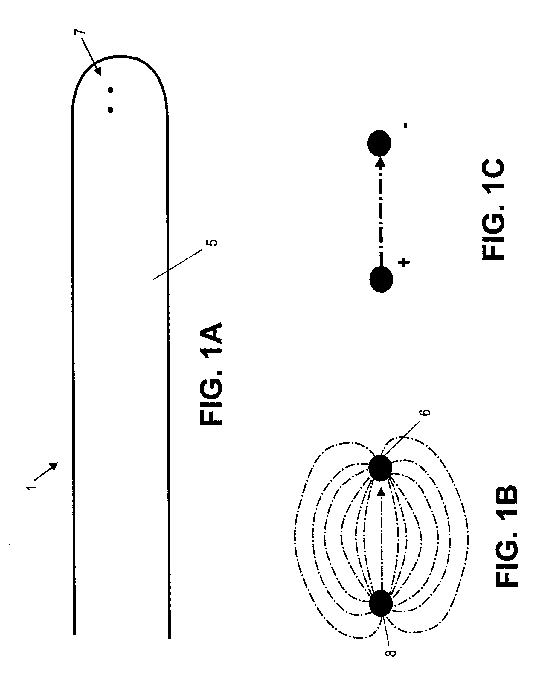
[0167]FIG. 21 is a top view of a vertebr...


PUM


Abstract

Described herein are devices, systems and methods for determining if a nerve is nearby a device or a region of a device. In general, a device for determining if a nerve is nearby a device includes an elongate body having an outer surface with one or more bipole pairs arranged on the outer surface. Bipole pairs may also be referred to as tight bipoles. The bipole pairs may be arranged as a bipole network, and may include a cathode and an anode that are spaced relatively close together to form a limited broadcast field. In general, the broadcast filed is a controlled or “tight” broadcast field that extends from the bipole pair(s). Methods of using these devices and system are also described.

Description

CROSS-REFERENCE TO RELATED APPLICATIONS[0001]This application claims priority to U.S. Provisional patent application Ser. No. 61 / 020,670, titled “DEVICES AND METHODS FOR TISSUE LOCALIZATION AND IDENTIFICATION”, filed on Jan. 11, 2008; U.S. Provisional Patent Application Ser. No. 61 / 017,512, titled “METHOD, SYSTEM AND APPARATUS FOR TISSUE LOCALIZATION AND IDENTIFICATION”, filed on Dec. 28, 2007; U.S. Provisional Patent Application Ser. No. 60 / 976,029, titled “METHOD AND APPARATUS FOR NEURAL LOCALIZATION”, filed on Sep. 28, 2007; and U.S. Provisional Patent Application Ser. No. 60 / 970,458, titled “NERVE TISSUE LOCALIZATION SYSTEM”, filed on Sep. 6, 2007. Each of these provisional patent applications is herein incorporated by reference in its entirety.BACKGROUND OF THE INVENTION[0002]Many types of surgical intervention require manipulation of one or more medical devices in close proximity to a nerve or nerves, and therefore risk damage to the nerve tissue. For example, medical devices ...

Claims


Application Information

Patent Timeline
Patent Type & Authority Patents(United States)
IPC IPC(8): A61B5/05
CPCA61B5/0488A61B5/1104A61B5/4893A61B5/4041A61B5/4504A61B2562/0209A61B2562/0261A61B2562/043A61B2562/046A61B5/6855A61B5/389
Inventor SCHMITZ, GREGORY P.WALLACE, MICHAEL P.BLEICH, JEFFERY L.MILLER, ERIC C.
Owner MIS IP HLDG LLC
Why Eureka
Try Eureka