Magnetic floating gate memory

a floating gate memory and magnetic technology, applied in digital storage, semiconductor devices, instruments, etc., can solve the problems of inefficient electron injection via hot electron injection, short travel time beneath the floating gate of the fet,

Inactive Publication Date: 2011-06-14
SEAGATE TECH LLC
View PDF8 Cites 2 Cited by
  • Summary
  • Abstract
  • Description
  • Claims
  • Application Information

AI Technical Summary

Benefits of technology

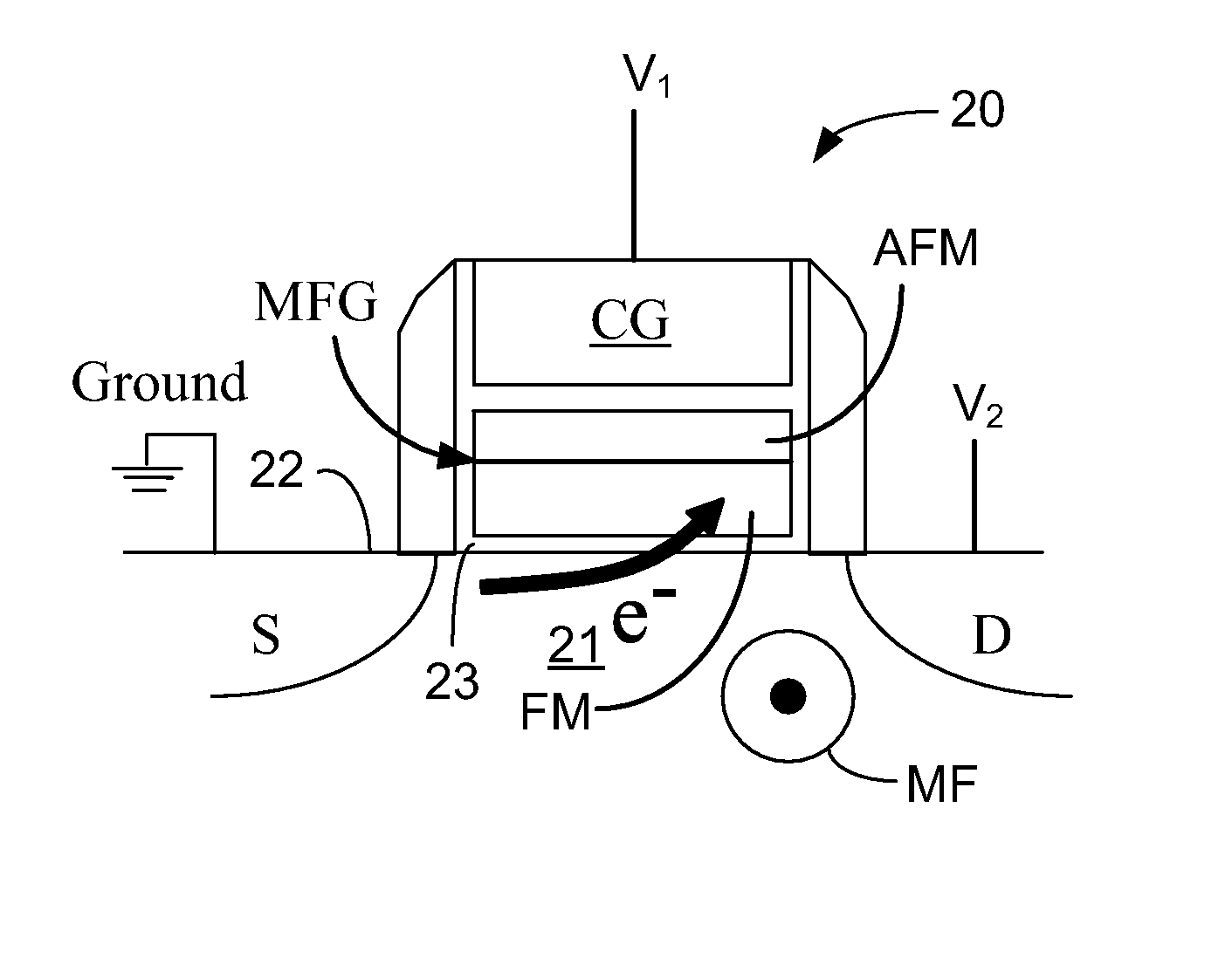
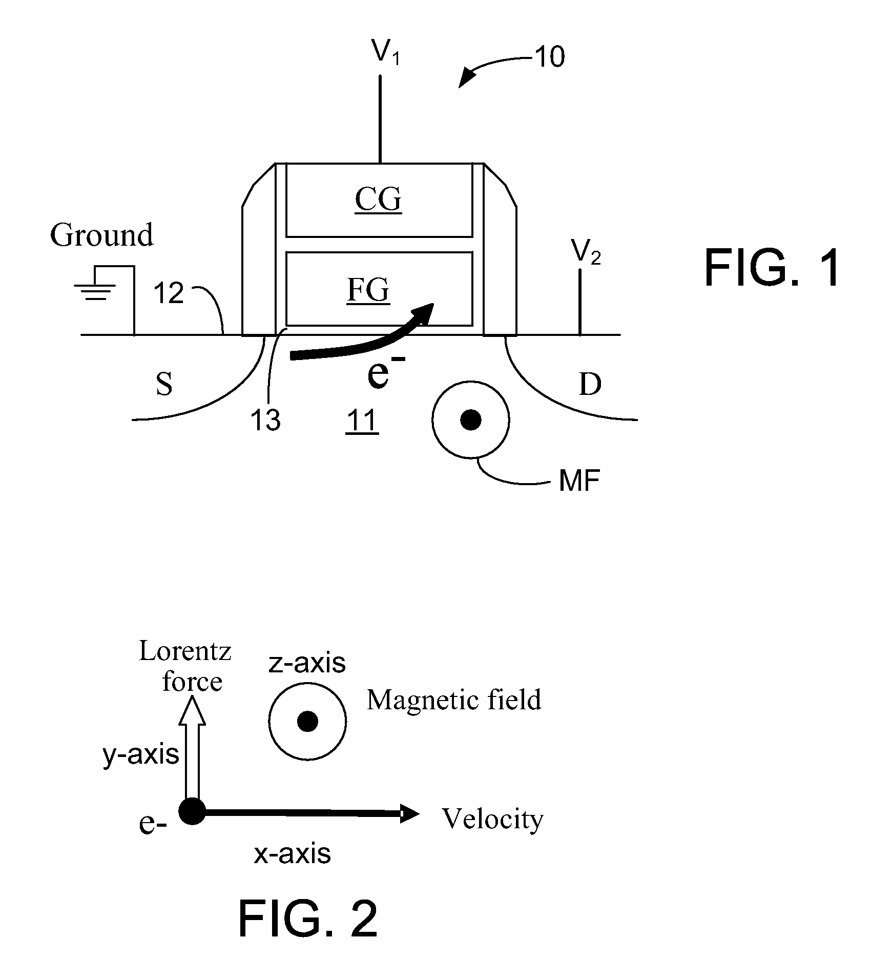
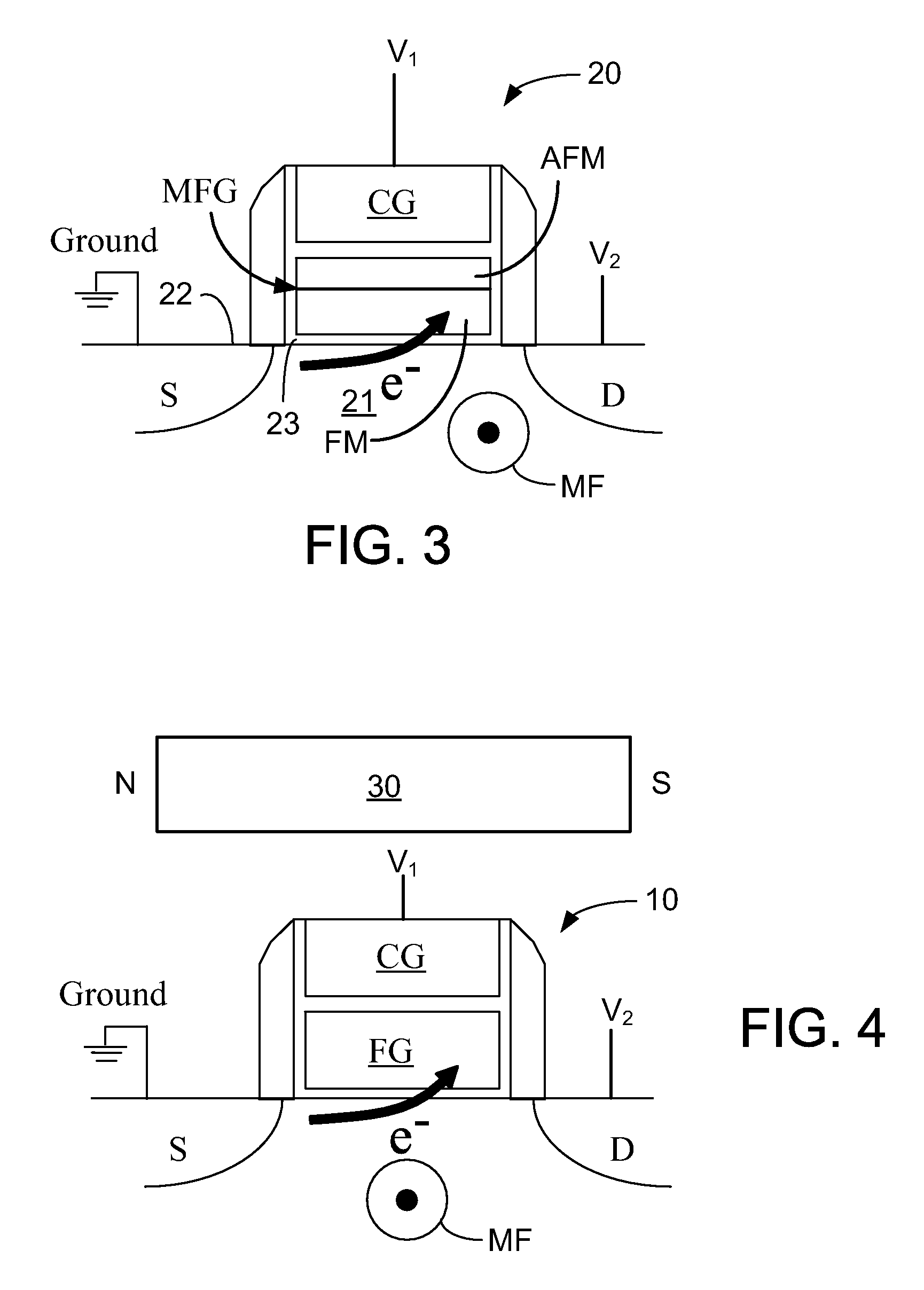
[0003]The present disclosure relates to magnetic floating gate memory with improved electron injection efficiency. In particular the present disclosure relates to magnetic floating gate memory that generates a magnetic field that is perpendicular to a hot electron travel direction between a source region and a drain region and perpendicular to a hot electron injection direction. The magnetic field bends the hot electron travel direction by a Lorentz's force, directing it into the floating gate of a FET through the hot electron injection direction.

Problems solved by technology

As the hot electrons move very fast, their travel time beneath the floating gate of the FET is too short to attract many of the hot electrons into the floating gate of the FET.
Thus, electron injection via hot electron injection is not very efficient.

Method used


Image

  • Magnetic floating gate memory
  • Magnetic floating gate memory
  • Magnetic floating gate memory

Examples


Embodiment Construction

[0016]In the following description, reference is made to the accompanying set of drawings that form a part hereof and in which are shown by way of illustration several specific embodiments. It is to be understood that other embodiments are contemplated and may be made without departing from the scope or spirit of the present disclosure. The following detailed description, therefore, is not to be taken in a limiting sense. The definitions provided herein are to facilitate understanding of certain terms used frequently herein and are not meant to limit the scope of the present disclosure.

[0017]Unless otherwise indicated, all numbers expressing feature sizes, amounts, and physical properties used in the specification and claims are to be understood as being modified in all instances by the term “about.” Accordingly, unless indicated to the contrary, the numerical parameters set forth in the foregoing specification and attached claims are approximations that can vary depending upon the ...


PUM


Abstract

An apparatus includes at least one memory device including a floating gate element and a magnetic field generator that operably applies a magnetic field to the memory device. The magnetic field directs electrons in the memory device into the floating gate element.

Description

BACKGROUND[0001]Field-effect transistors (FET) has been considered to be an ideal technology for nonvolatile memory because of its random access, high speed, low power, high density and simplicity. For a nonvolatile semiconductor storage device in which each memory cell is composed of an FET provided with a floating gate covered by an insulating film and used as a charge storing layer, data is stored by controlling the amount of electrons stored in the floating gate thereby changing the threshold voltage of the transistor. When programming or erasing data into or from the memory cell, electrons are either injected or ejected from the floating gate via the insulating film.[0002]Electron injection / ejection is possible by using the (Fowler-Nordheim (F-N)) tunnel phenomenon and the hot electron phenomenon. Electrons are injected in the insulating film around the floating gate with the application of a high electrical field. In the case of hot electron injection, an electric field betwee...

Claims


Application Information

Patent Timeline
Patent Type & Authority Patents(United States)
IPC IPC(8): G11C11/00
CPCG11C11/14G11C16/0408H01L21/28273H01L29/7881H01L29/82H01L29/66825H01L29/40114
Inventor JIN, INSIKLI, YANGLIU, HONGYUEXUE, SONG S.
Owner SEAGATE TECH LLC
Why Eureka
Try Eureka