Systems and methods for improving drivetrain efficiency for compressed gas energy storage

a technology of compressed gas and drivetrain, applied in the direction of electric generator control, fluid coupling, positive displacement liquid engine, etc., can solve the problems of reducing system efficiency, reducing system efficiency, and/or irregular power output, so as to improve efficiency, increase the efficiency of electric motor and generator, and improve the effect of system efficiency

Inactive Publication Date: 2011-06-21
SUSTAINX
View PDF772 Cites 57 Cited by
  • Summary
  • Abstract
  • Description
  • Claims
  • Application Information

AI Technical Summary

Benefits of technology

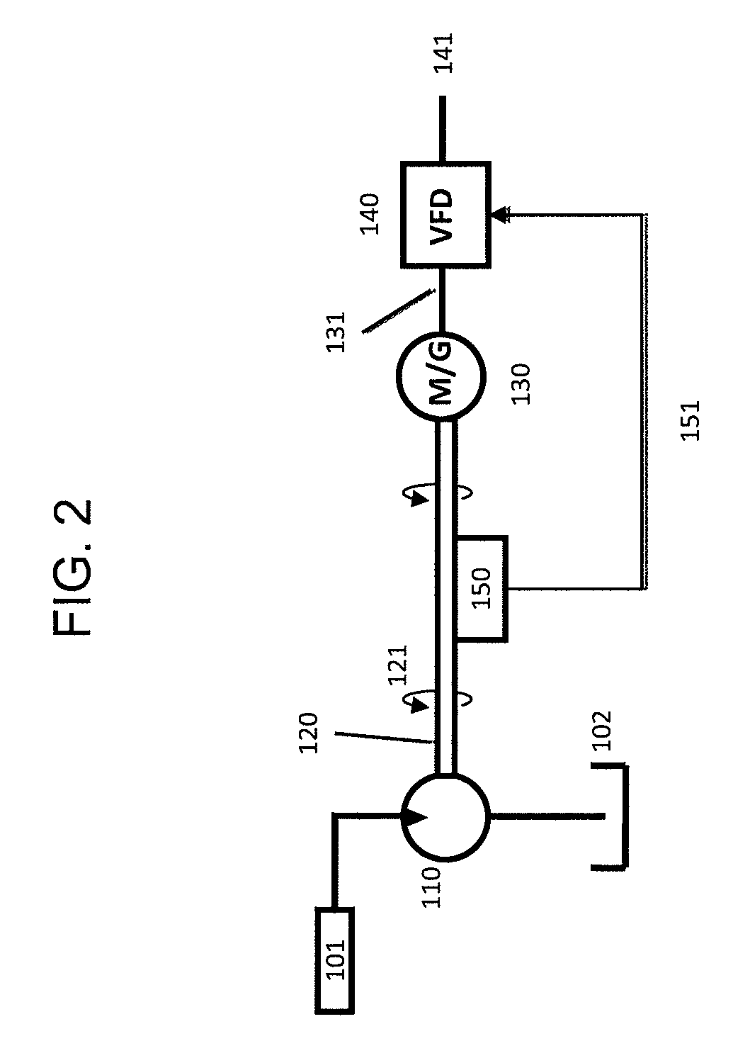
[0016]Additionally, the control system can be used to vary electrical load on the generator. That is, the control system may be configured to increase the RPM of an electric generator by controlling a VFD in such a way as to modify the generator's load in response to decreasing torque on its shaft. Constant power output from the electric generator is thereby maintained and the output voltage of the electric generator can be synchronized to a power grid. Additionally, or alternatively, the control system can be used to vary the mechanical load on the hydraulic motor. The control system may be configured to increase the RPM of the hydraulic motor by adjusting the CVT in such a way as to decrease the hydraulic motor's load in response to decreasing torque on its shaft. Motor RPM consequently increases, constant power output from the electric generator is maintained, and the output voltage of the electric generator can be synchronized to a power grid.
[0017]Other systems and methods for providing constant power, improving efficiency, and overcoming the limitations of fixed displacement motors when operating over a wide pressure range include using active control with a VD hydraulic motor. For example, efficiency for an electric motor-generator can vary substantially based on torque and RPM; when the hydraulic motor-pump in the staged hydraulic conversion system is attached to an electric motor-generator, it would be advantageous to operate at a narrow range or fixed value for RPM (e.g. 1800 RPM) and torque to operate at peak efficiency, increasing electric motor, and thus system, efficiency. Likewise, operating at a fixed RPM and power (and thus constant voltage, frequency, and current for an electric generator) during system discharge would allow an electric generator to be synchronized with the grid and potentially eliminate additional power conditioning equipment that would be required for a variable frequency, variable voltage, and / or variable power output. By using the VD hydraulic motor-pump in lieu of the FD hydraulic motor, the displacement per revolution can be controlled in such a way as to maintain a nearly constant torque and proportionally increasing flow rate such that the RPM and power output are kept nearly constant. For the novel compressed air energy storage and recovery system using staged hydraulic conversion described in the above-referenced applications, this constant RPM and power allows for a reduction in electric system costs by potentially eliminating power conditioning equipment necessary for a variable frequency, voltage, or power output, while at the same time improving overall system efficiency by operating at the peak efficiency region of the electric generator; likewise, the increasing flow rate maintains a nearly constant power throughout a decreasing pressure range, also adding value to the energy storage and recovery system.
[0018]Furthermore, high efficiency standard commercial variable displacement motor-pump designs include radial piston style (external cam), which are used primarily at low speeds, and axial piston styles (swash-plate, bent-axis). For axial piston motors, the piston assembly typically rotates in an oil bath; for large displacement axial piston motors, viscous drag (which is proportional to speed squared) limits efficiency at high rotational speeds. Additionally, for the radial and axial piston styles displacement is reduced by reducing piston stroke; as piston stroke drops below half the total possible stroke, efficiency typically drops substantially. As described herein, newly developed VD hydraulic motor-pumps which use digital control to open and close valves to control displacement are able to achieve substantially higher efficiencies at large displacement sizes (no longer rotating the entire piston assembly in an oil bath) and maintain high efficiency at low relative displacements (by not changing piston stroke length). In these digitally controlled pumps / motors, relative displacement is controlled by actively opening and closing valves to each piston, such that each piston may or may not be exposed to high pressure each time the rotating cam completes a revolution. Unlike the standard commercial VD motor-pumps, the piston always completes a full stroke, maintaining high motor-pump efficiency even at low relative displacements.
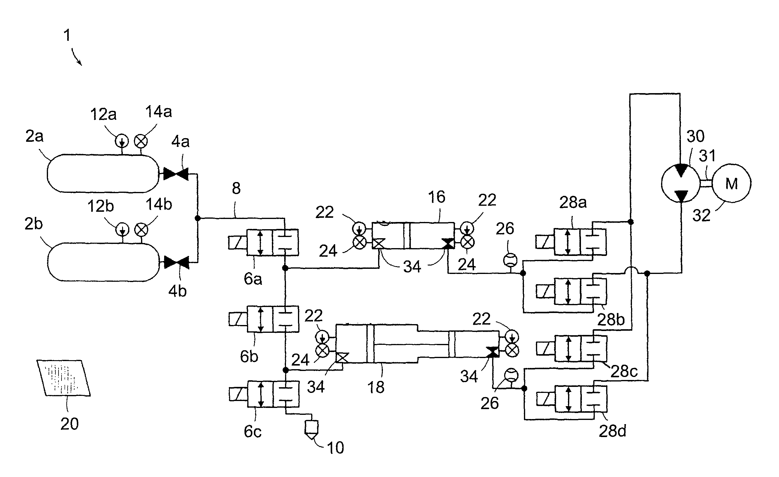
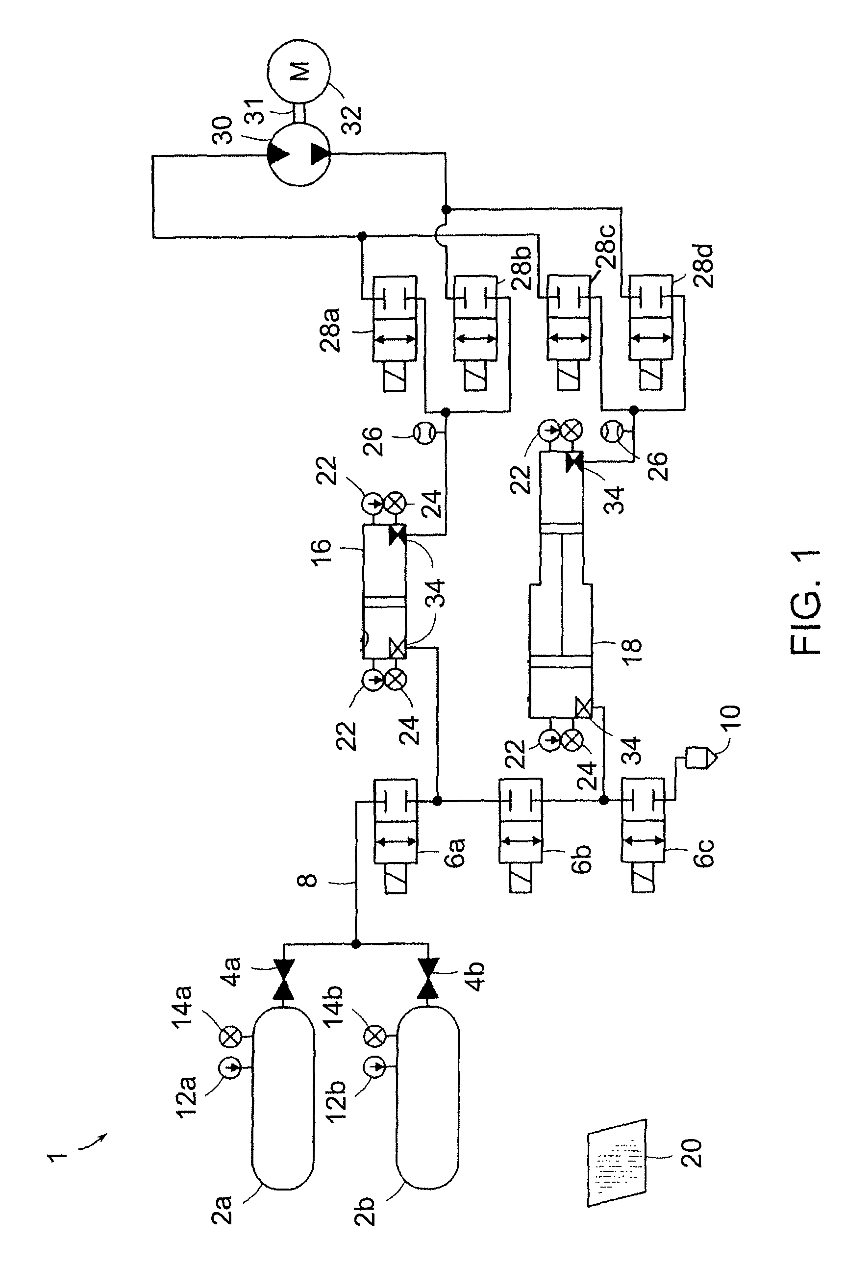
[0019]In one aspect, the invention relates to a system for providing a constant electrical output from a compressed gas energy storage and recovery system. The system includes a hydraulic-pneumatic energy storage and recovery system configured to provide a varying pressure profile at, at least one outlet, a variable displacement hydraulic motor-pump in fluid communication with the at least one outlet, and a control system in communication with the variable displacement hydraulic motor-pump. The control system controls at least one variable, such as pressure, piston position, power, flow rate, torque, RPM, current, voltage, frequency, and displacement per revolution. The use of the variable displacement hydraulic motor and associated control system allow a user to achieve near constant expansion and compression power in the hydraulic-pneumatic energy storage and recovery system, while maintaining near constant RPM or torque at the shaft of an electric motor-generator.

Problems solved by technology

However, recovering the energy from the stored compressed gas has certain drawbacks.
For example, systems that utilize pneumatic to hydraulic conversion to drive a hydraulic motor are subject to a decaying pressure profile, which in turn produces decreasing and / or irregular power output.
The disadvantage with this approach is that a significant amount of energy is lost and converted to heat in the throttling valves, greatly reducing system efficiency.
The prior art does not disclose systems and methods for providing constant electrical power with a staged hydraulic-pneumatic energy conversion system having hydraulic outputs having widely-varying pressures.

Method used


Image

  • Systems and methods for improving drivetrain efficiency for compressed gas energy storage
  • Systems and methods for improving drivetrain efficiency for compressed gas energy storage
  • Systems and methods for improving drivetrain efficiency for compressed gas energy storage

Examples


Embodiment Construction

[0062]FIG. 1 depicts generally a basic hydraulic-pneumatic energy conversion system 1 that stores and recovers electrical energy using at least one hydraulic motor. Various hydraulic-pneumatic energy conversion systems are described in detail in the above incorporated patent applications. The system 1 includes one or more high-pressure gas / air storage tanks 2a, 2b, . . . 2n. Each tank 2 is joined in parallel via a manual valve(s) 4a, 4b, . . . 4n, respectively, to a main air line 8. The valves 4 are not limited to manual operation, as the valves can be electrically, hydraulically, or pneumatically actuated, as can all of the valves described herein. The tanks 2 are each provided with a pressure sensor 12a, 12b . . . 12n and a temperature sensor 14a, 14b . . . 14n. These sensors 12, 14 can output electrical signals that can be monitored by a control system 20 via appropriate wired and wireless connections / communications. Additionally, the sensors 12, 14 could include visual indicator...


PUM


Abstract

In various embodiments, systems for providing a constant electrical output from a compressed gas energy storage and recovery system include a hydraulic-pneumatic energy storage and recovery system configured to provide a varying pressure profile at least at one outlet, a hydraulic motor-pump in fluid communication with the outlet, and a control system for enabling the constant electrical output by controlling at least one of pressure, piston position, power, flow rate, torque, RPM, current, voltage, frequency, or displacement per revolution.

Description

CROSS-REFERENCE TO RELATED APPLICATIONS[0001]This application claims priority to U.S. Provisional Patent Application Ser. Nos. 61 / 159,623, filed on Mar. 12, 2009; 61 / 227,591, filed on Jul. 22, 2009; and 61 / 229,853, filed on Jul. 30, 2009, the disclosures of which are hereby incorporated herein by reference in their entireties.STATEMENT REGARDING FEDERALLY SPONSORED RESEARCH[0002]This invention was made with government support under IIP-0810590 and IIP-0923633 awarded by the NSF. The government has certain rights in the invention.FIELD OF THE INVENTION[0003]The invention relates to hydraulics and pneumatics, power generation, and control systems. More particularly, the invention relates the integration of variable and fixed displacement hydraulic motor-pumps in hydraulic-pneumatic energy storage and recovery systems and related control systems and methods to provide constant electrical power therefrom.BACKGROUND OF THE INVENTION[0004]Storing energy in the form of compressed gas has a...

Claims


Application Information

Patent Timeline
Patent Type & Authority Patents(United States)
IPC IPC(8): F04B49/00
CPCF15B1/024F15B21/08F15B21/14H02P9/04F15B2211/20515F15B2211/20569F15B2211/212F15B2211/6309F15B2211/6655H02J15/006F15B2211/216
Inventor BOLLINGER, BENJAMIN R.MCBRIDE, TROY O.SCHAEFER, MICHAEL
Owner SUSTAINX
Why Eureka
Try Eureka