Ultrasonic probe

a technology of ultrasonic probes and probes, applied in the field of ultrasonic probes, can solve the problems of significant reduction of the ultrasonic wave characteristics of the probe, oil leakage from the sealed container b, /b>, air bubbles, etc., and achieve excellent ultrasonic characteristics

Inactive Publication Date: 2011-06-21
NIHON DEMPA KOGYO CO LTD
View PDF19 Cites 2 Cited by
  • Summary
  • Abstract
  • Description
  • Claims
  • Application Information

AI Technical Summary

Benefits of technology

[0016]An object of the present invention is to provide an ultrasonic probe that prevents an occurrence of air bubbles in a liquid that serves as an ultrasonic wave medium, and that realizes excellent ultrasonic characteristics.

Problems solved by technology

However, in the conventional short axis oscillating probe configured as described above, for example as pointed out in Japanese Unexamined Patent Publication No. 2005-334107, there has been a problem in that the oil L filled within the sealed container 103 expands and contracts due to temperature change, causing oil leakage from the sealed container 103 and air bubbles.
As a result, attenuation of the ultrasonic waves becomes significant, resulting in a significant reduction in the ultrasonic wave characteristics of the probe.
Therefore, there is the problem described below.
As a result, there is a problem in that when filling the pre-degassed oil L, air inside the sealed container 103 is mixed in the oil L and cannot be completely discharged, causing the air to remain in the oil L as air bubbles.
However, air bubbles still occur even in this case.
Therefore it becomes difficult to remove air bubbles that have occurred inside the diaphragm 112 when injecting the oil L.
As a result, there has been a problem in that it is difficult to remove air bubbles that occur when filling the oil L, and to fully fill up only with oil, only by providing the diaphragm 112 in the sealed container 103 in addition to the inlet hole 110.
These problems are observed not only in a short axis oscillating probe intended to comprise a piezoelectric element group (array type), but also for example in an ultrasonic probe with the piezoelectric elements in a circular shape as a single plate so as to perform mechanical scanning.
In short, a problem occurs when filling a liquid that serves as an ultrasonic wave medium within the sealed container.

Method used


Image

  • Ultrasonic probe
  • Ultrasonic probe
  • Ultrasonic probe

Examples


Embodiment Construction

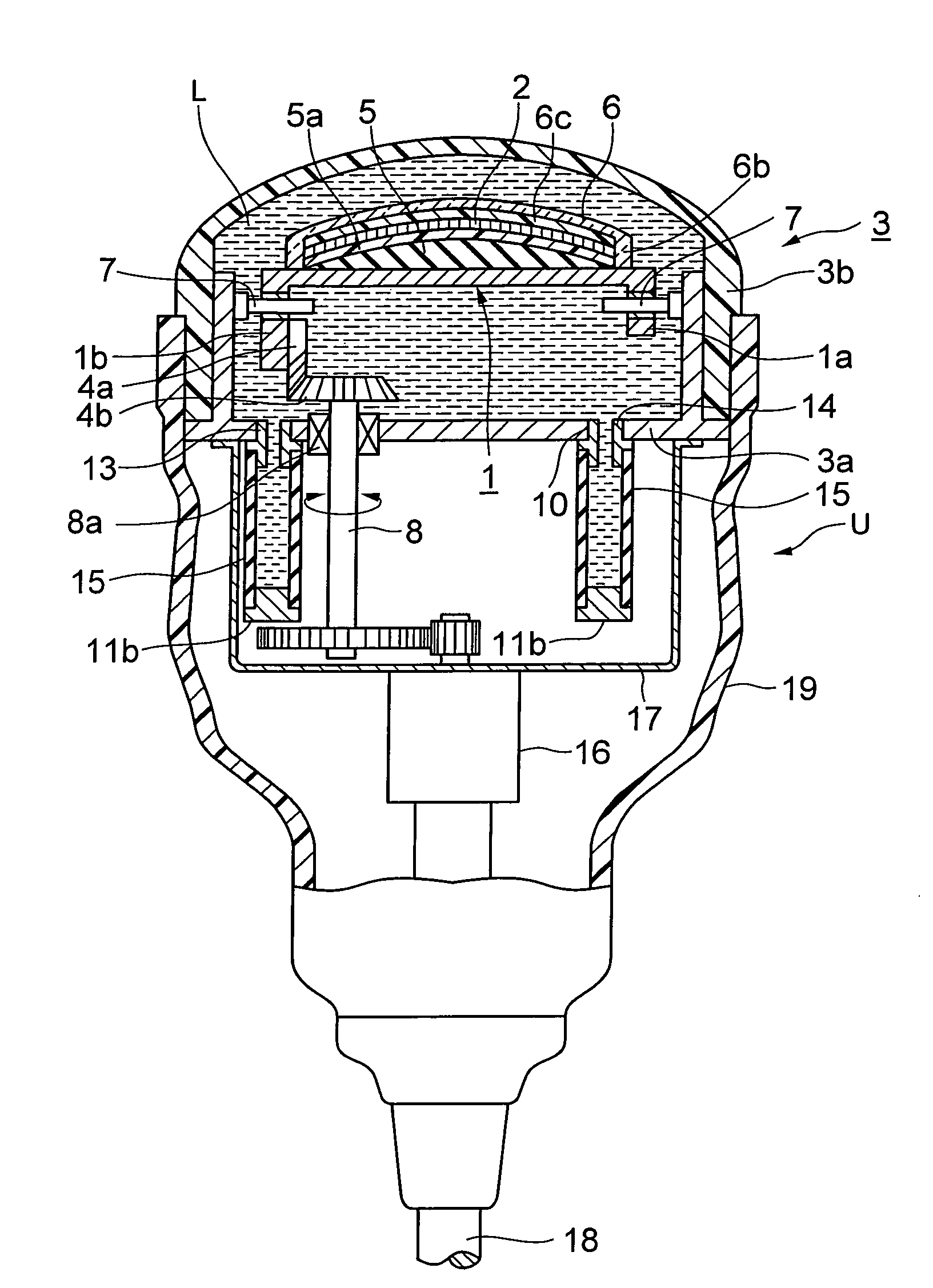
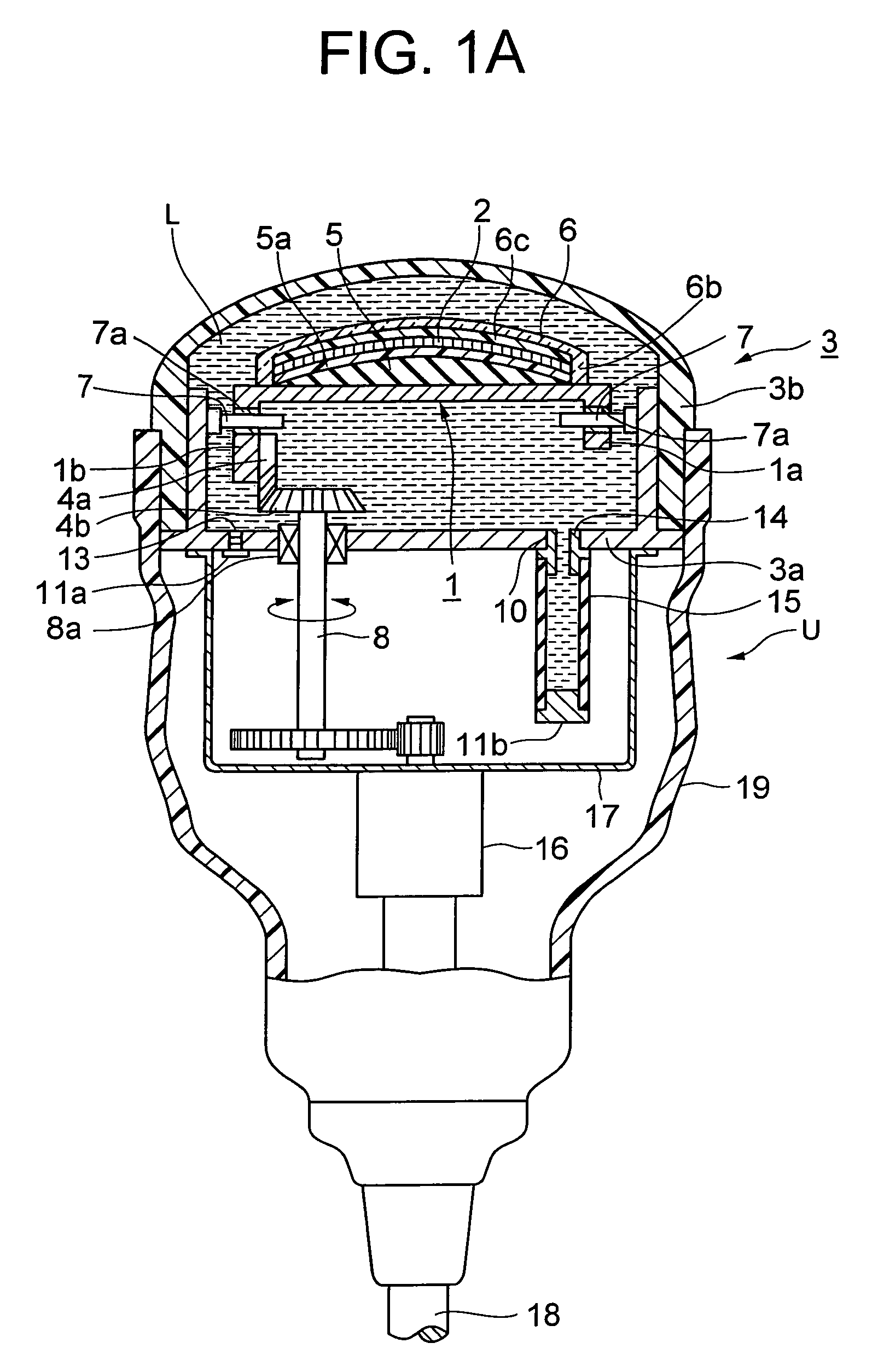
[0026]FIG. 1A is a sectional view in the long axis direction for explaining an embodiment of a short axis oscillating probe of the present invention.

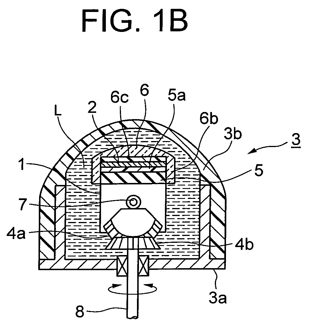
[0027]The short axis oscillating probe of the present invention is such that a piezoelectric element group 2 arranged in the long axis direction is provided on a horizontal section of a sectionally channel shaped rotational retention base 1, so as to be housed within a sealed container 3 comprising a container main body 3a and a cover 3b that are both sectionally concave shaped. In leg sections la and lb on both end sides of the rotational retention base 1, there is respectively provided a bearing 7a so as to slidably engage with a pair of rotational center shafts 7 provided, in the long axis direction, on the side walls of the container main body 3a.

[0028]A first bevel gear 4a that is provided on one leg section 1b of the rotational retention base 1 and that rotates and oscillates in the short axis direction, meshes with a second beve...


PUM

PropertyMeasurementUnit
flexibleaaaaaaaaaa
ultrasonicaaaaaaaaaa
piezoelectricaaaaaaaaaa

Abstract

An ultrasonic probe is configured such that: a piezoelectric element group is housed within a sealed container so as to be rotated and oscillated left and right about a center line that equally divides a plate surface of the piezoelectric element group; and the sealed container is filled with a liquid that serves as an acoustic medium, and in the sealed container there are provided an inlet hole for the liquid as well as an exhaust hole, to the inlet hole there is connected a flexible tube that functions as a diaphragm, and on the flexible tube and the exhaust hole there are respectively provided sealing lids. As a result, there is provided an ultrasonic probe that prevents an occurrence of air bubbles in a liquid that serves as an ultrasonic wave medium, and that realizes excellent ultrasonic characteristics.

Description

TECHNICAL FIELD[0001]The present invention relates to an ultrasonic probe in which a liquid serving as an ultrasonic wave medium is filled within a sealed container so as to perform mechanical scanning, in particular, to a short axis oscillating type ultrasonic probe (hereinafter, referred to as “short axis oscillating probe”) that rotates and oscillates a piezoelectric element group in the short axis direction to obtain a three dimensional image of an examination subject.BACKGROUND ART[0002]1. Background of the Invention[0003]A short axis oscillating probe is known as a probe that electronically scans a piezoelectric element group in the short axis direction thereof, and mechanically scans (oscillates) in the short axis direction thereof to obtain a three dimensional image of an examination subject (refer to Japanese Examined Patent Publication No. Hei 7-38851, Japanese Unexamined Patent Publication No. 2003-175033, Japanese Patent Application No. 2005-175700, and Japanese Unexamin...

Claims


Application Information

Patent Timeline
Patent Type & Authority Patents(United States)
IPC IPC(8): G01N29/24
CPCG10K11/02A61B8/4461A61B8/483A61B8/4281A61B8/12A61B8/13
Inventor HASEGAWA, YASUNOBU
Owner NIHON DEMPA KOGYO CO LTD
Why Eureka
Try Eureka