
Boiler and method for controlling air and fuel ratio using air pressure sensor

a technology of air pressure sensor and air fuel ratio, which is applied in the direction of motor/generator/converter stopper, dynamo-electric converter control, etc., can solve the problems of the inability to control the optimal combustion efficiency or optimally maximized air-fuel ratio, and the inability to control the optimal combustion efficiency and precise air-fuel ratio. achieve the effect of minimizing the discharge of harmful gases

Inactive Publication Date: 2011-06-21
KYUNGDONG ONE CORP
View PDF9 Cites 0 Cited by
  • Summary
  • Abstract
  • Description
  • Claims
  • Application Information

AI Technical Summary

Benefits of technology

[0015]As described above, according to the air-fuel ratio control boiler using a air pressure sensor and the method for controlling the air-fuel ratio thereof, it is possible not only to improve the precise control over the boiler, but also maximize the combustion efficiency. Thereby, it is possible to minimize discharge of harmful gases and exert optimal fuel efficiency improvement effects.
[0016]This increase in the effectiveness of the air-fuel ratio makes it possible to raise the reliability of products.

Problems solved by technology

However, the conventional boiler has disadvantages in that an initial reference voltage value is varied with the arrival of hot / cold weather, that sensor properties are varied when used for a long time, and that an initial reference value is varied by dust or foreign materials on the reflecting member, variation of the resilient force of the elastic member, and so on.
In other words, the conventional boiler fails to eliminate various noise factors, such as property deviation of the air pressure sensor, deviation caused by resilient property of the spring or the elastic member, deviation caused by colors of the reflecting member, deviation caused by the rubber property of the diaphragm, and so on, so that it cannot control the optimal combustion efficiency or optimally maximized air-fuel ratio.
Thereby, it is impossible to control the optimal combustion efficiency and the precise air-fuel ratio.
Furthermore, the reliability of the products is lowered.

Method used


Image

  • Boiler and method for controlling air and fuel ratio using air pressure sensor
  • Boiler and method for controlling air and fuel ratio using air pressure sensor
  • Boiler and method for controlling air and fuel ratio using air pressure sensor

Examples


Embodiment Construction

[0024]Reference will now be made in detail to the exemplary embodiments of the present invention.

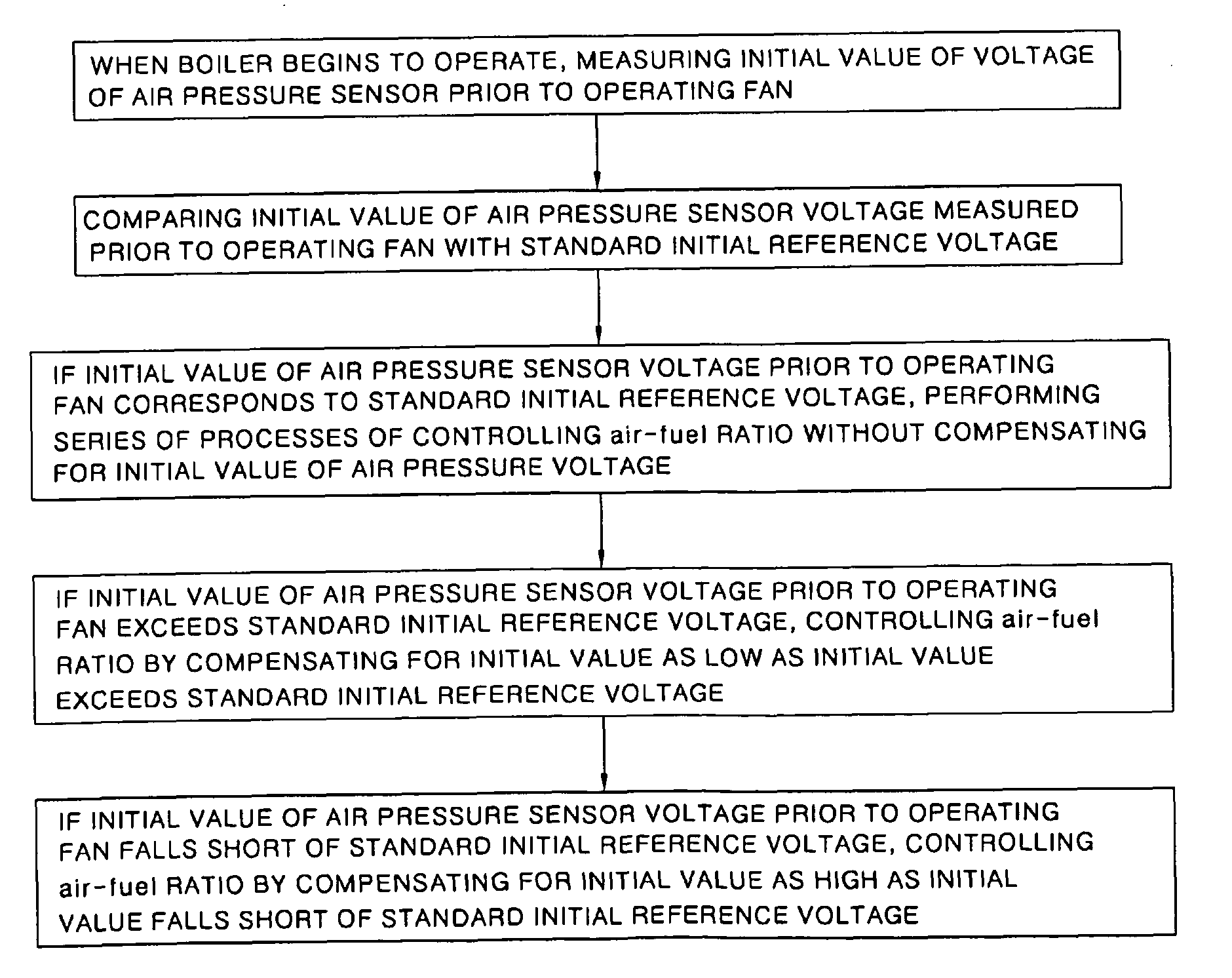
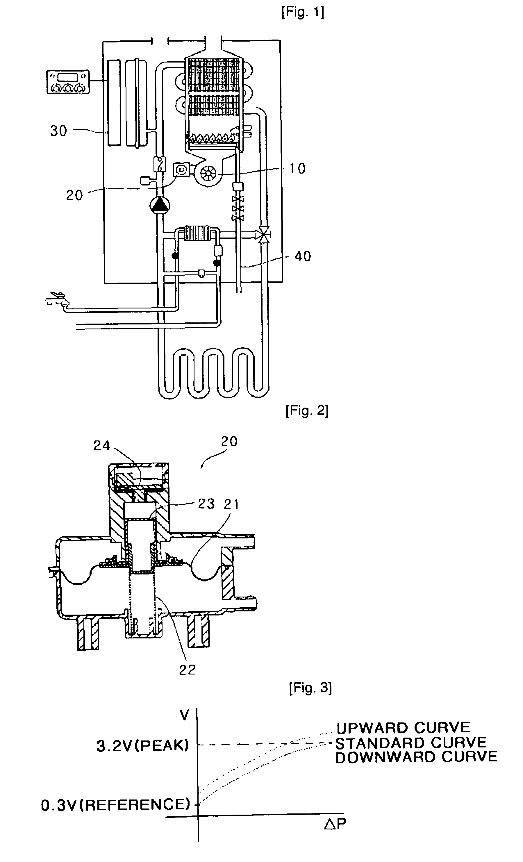
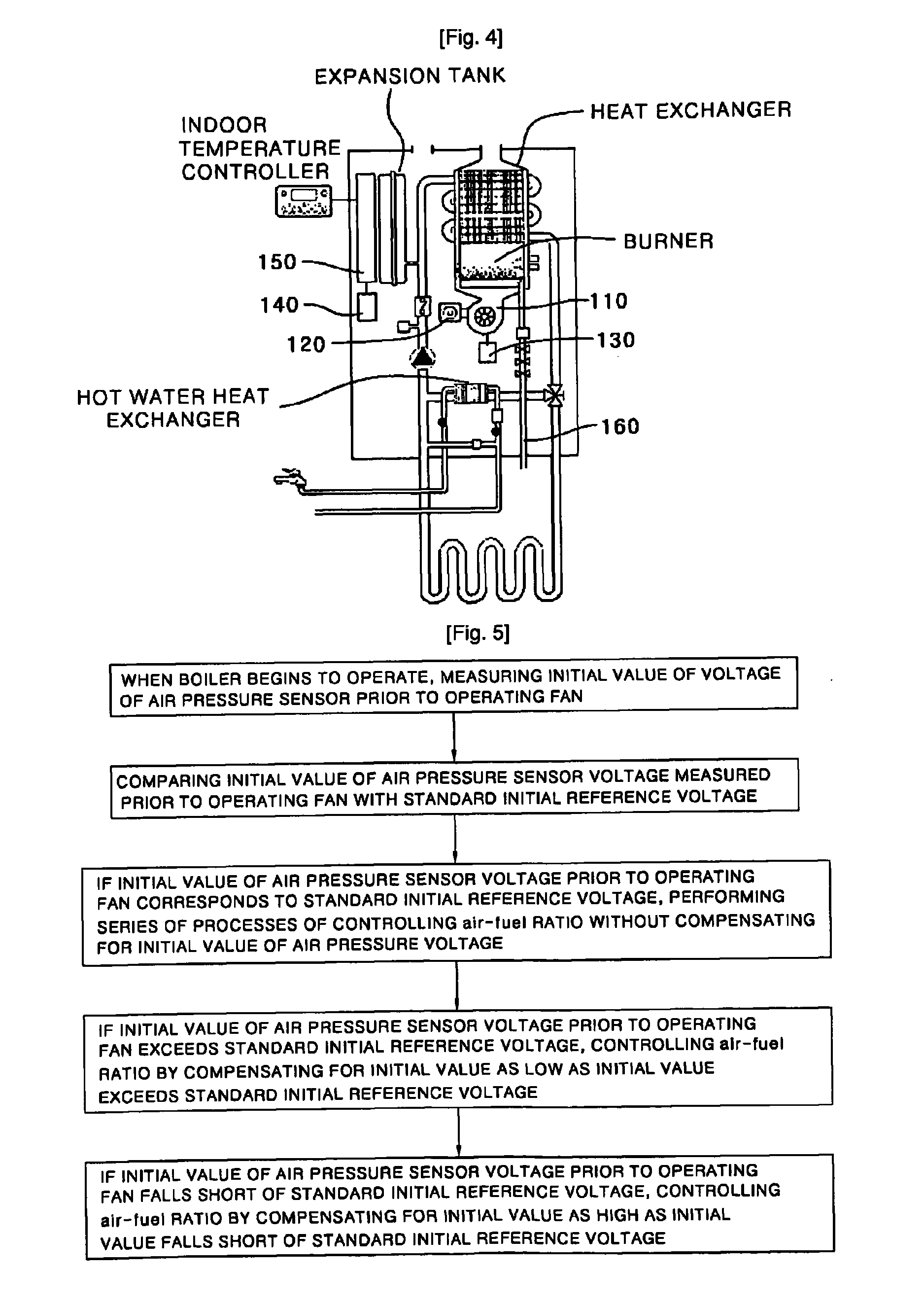
[0025]FIG. 4 illustrates a schematic construction of an air-fuel ratio control boiler using a air pressure sensor in accordance with the present invention. FIG. 5 is a block flowchart illustrating a method for controlling an air-fuel ratio of a boiler using a air pressure sensor in accordance with the present invention. FIG. 6 is a voltage-to-pressure graph for explaining air-fuel ratio control according to the present invention.

[0026]As illustrated in FIG. 4, the air-fuel ratio control boiler using a air pressure sensor in accordance with the present invention is comprised of a fan 110 that sucks in air for combustion and is provided with a venturi tube on an air passage so as to generate differential pressure, the air pressure sensor 120 that is connected with the venturi tube of the fan 110 and measures pressure of the air using the differential pressure generated at the venturi tube,...


PUM


Abstract

Disclosed is an air-fuel ratio control boiler using a air pressure sensor and method for controlling the air-fuel ratio thereof. The boiler is comprised of a fan, the air pressure sensor, a air pressure sensor voltage measurement unit, a air pressure sensor voltage compensation unit, and a controller, and previously compensates for noise factors caused by deviation (error) of a component property, a constituent, of the air pressure sensor so as to be matched to initial reference voltage prior to operating the fan, thereby maximizing the effectiveness of the air-fuel ratio. Further, the boiler makes it possible not only to exert an optimal fuel efficiency effect due to the maximization of combustion efficiency, but also to minimize discharge of harmful gases, thereby preventing environmental pollution in advance, and thus improving the reliability of products.

Description

TECHNICAL FIELD[0001]The present invention relates to an air-fuel ratio control boiler using a air pressure sensor and method for controlling the air-fuel ratio thereof, and more particularly to an air-fuel ratio control boiler using a air pressure sensor and method for controlling the air-fuel ratio thereof, capable of realizing optimal combustion efficiency and precise air-fuel ratio control to improve fuel efficiency of the boiler, and greatly increasing effectiveness to raise the reliability of products.BACKGROUND ART[0002]In general, boilers are machines for mixing and burning air and fuel. In these burners, combustion efficiency is determined depending on how accurately the mixing ratio of the air and the fuel is controlled.[0003]In the boilers, an air proportional control system, or a current proportional control system is applied in order to control the air-fuel ratio. An accurate quantity of fuel is supplied in proportion to the pressure of air introduced by controlling the...

Claims


Application Information

Patent Timeline
Patent Type & Authority Patents(United States)
IPC IPC(8): H02P1/04F23N5/00F23L9/00
CPCF23N3/082F23N2033/08F23N2025/06F23N2225/06F23N2233/08F23N5/18F23N2005/181F24H1/22F24H9/2035
Inventor KIM, SI, HWAN
Owner KYUNGDONG ONE CORP
Learn More