Method and apparatus for measuring the switching current of power converter operated at continuous current mode

a technology of power converter and continuous current, applied in the direction of power supply testing, process and machine control, instruments, etc., can solve the problems of sampling error, voltage spike and noise generation

Active Publication Date: 2011-06-21
SEMICON COMPONENTS IND LLC
View PDF4 Cites 33 Cited by
  • Summary
  • Abstract
  • Description
  • Claims
  • Application Information

AI Technical Summary

Problems solved by technology

A voltage spike and noise are generated at the rising edge of the switching current IP.
The voltage spike and noise will generate error for the sampling.

Method used


Image

  • Method and apparatus for measuring the switching current of power converter operated at continuous current mode
  • Method and apparatus for measuring the switching current of power converter operated at continuous current mode
  • Method and apparatus for measuring the switching current of power converter operated at continuous current mode

Examples


Embodiment Construction

The following description is of the best-contemplated mode of carrying out the invention. This description is made for the purpose of illustrating the general principles of the invention and should not be taken in a limiting sense. The scope of the invention is best determined by reference to the appended claims.

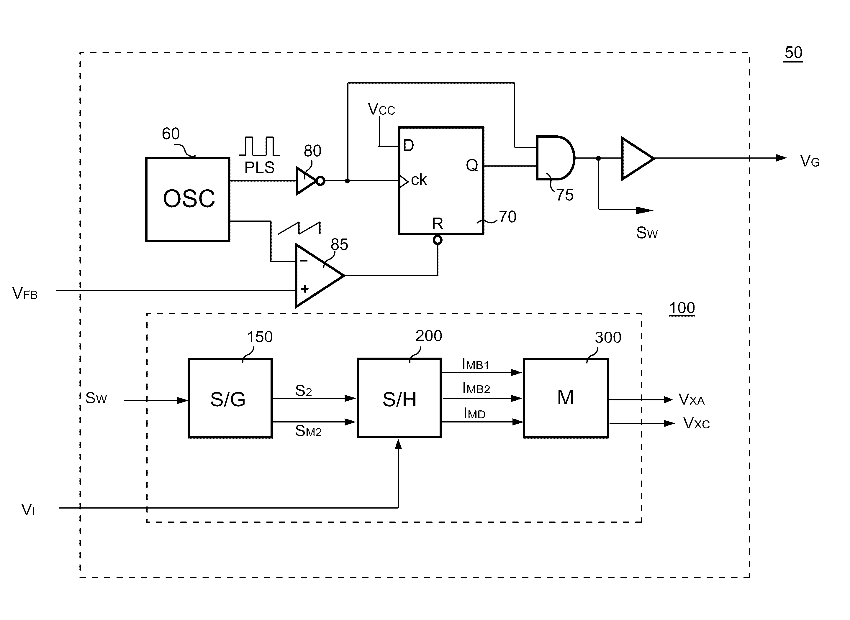
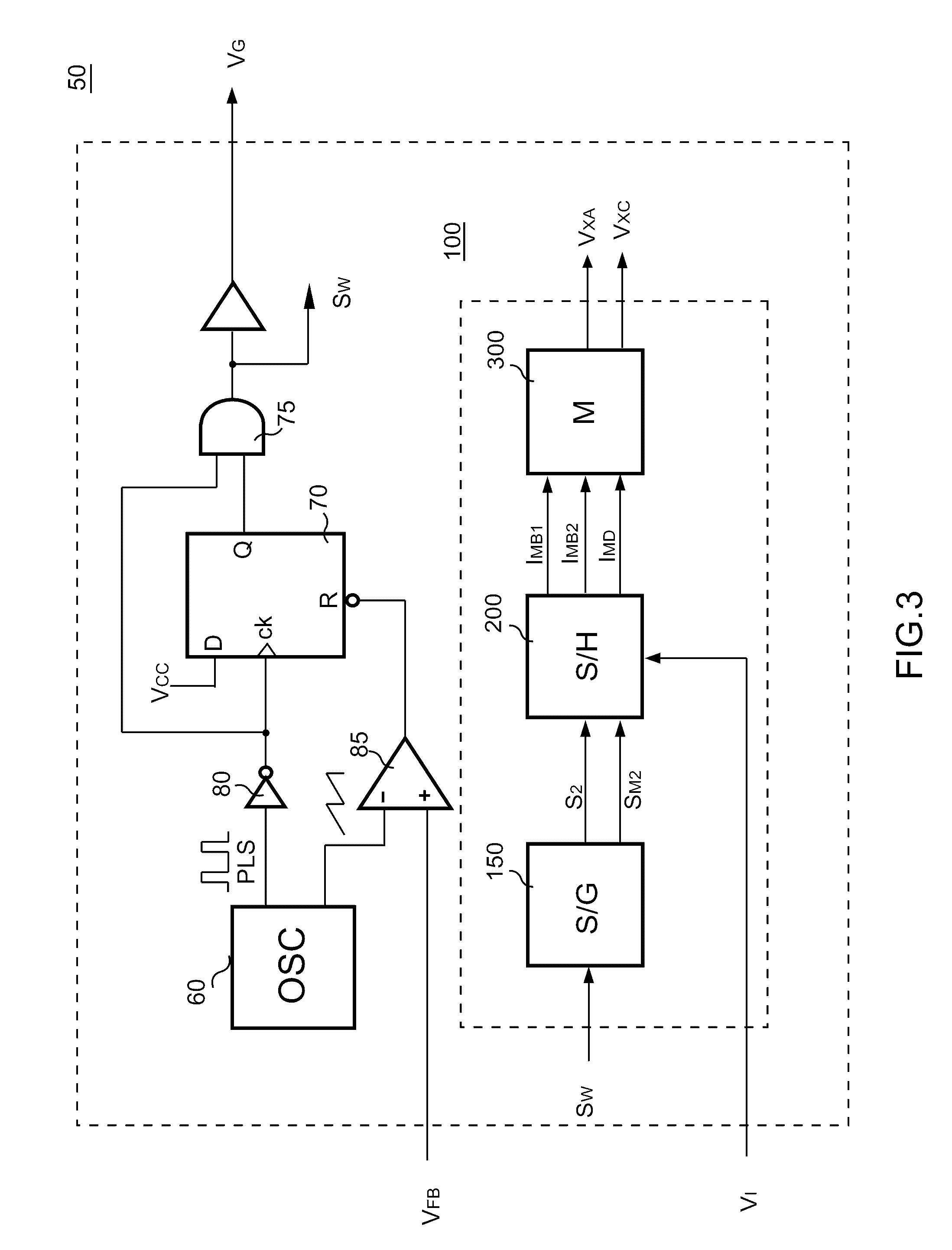
FIG. 3 is the circuit schematic of the controller 50 of the invention. A flip-flop 70 and an AND gate 75 generates switching signals SW and VG for driving the transistor 20 and switching the transformer 10 (shown in FIG. 1). A detection circuit 100 is coupled to receive the switching current signal VI for generating the DC-output signal VXA and the AC-output signal VXC. The detection circuit 100 includes a signal generation circuit 150, a sample-and-hold circuit 200 and a calculating circuit 300. The signal generation circuit 150 generates a sample signal S2 in accordance with the pulse width of the switching signal SW. The sample-and-hold circuit 200 is coupled to receive t...


PUM


Abstract

An apparatus for detecting a switching current of the power converter, wherein the apparatus includes a signal generation circuit, a sample-and-hold circuit, and a calculating circuit. The signal generation circuit generates a sample signal in accordance with the pulse width of a switching signal. The sample-and-hold circuit is coupled to receive the sample signal and switching current signal for generating a first current signal and a second current signal. The calculating circuit is coupled to receive the first current signal and the second current signal for generating output signals. The switching signal is used for switching the magnetic device of the power converter, and the switching current signal is correlated to the switching current of the power converter; the output signals are correlated to the value of the switching current of the power converter.

Description

BACKGROUND OF THE INVENTION1. Field of the InventionThe present invention relates generally to a switching control circuit, and more specifically to a method and apparatus for detecting a switching current of a power converter operated at continuous current mode.2. Description of the Related ArtA power converter is used to convert an unregulated power source to a regulated voltage or current source. The power converter normally includes a transformer or a magnetic device having a primary winding and a secondary winding to provide isolation. A switching device connected with the primary winding to control energy transfer from the primary winding to the secondary winding. FIG. 1 shows a conventional power converter. A controller 50 generates a switching signal VG to regulate the output of the power converter in response to a feedback signal VFB. The feedback signal VFB is correlated to the output VO of the power converter. The switching signal VG drives a power transistor 20 for switc...

Claims


Application Information

Patent Timeline
Patent Type & Authority Patents(United States)
IPC IPC(8): H02M3/24H02M7/44H02M3/335
CPCG01R19/0092H02M3/33507G01R31/40
Inventor YANG, TA-YUNGLI, CHUH-CHINGHSU, SHENG-FULIN, LICHEN, JUNG-SHENG
Owner SEMICON COMPONENTS IND LLC
Why Eureka
Try Eureka