Methods for making and using high explosive fills for MEMS devices

a filling and explosive technology, applied in the direction of explosives, weaving, looms, etc., can solve the problems of safety and performance problems, difficulty, safety and performance problems of fielded explosives, etc., and achieve the effect of improving the physical integrity of the loaded secondary explosiv

Inactive Publication Date: 2011-06-28
UNITED STATES OF AMERICA THE AS REPRESENTED BY THE SEC OF THE ARMY
View PDF2 Cites 6 Cited by
  • Summary
  • Abstract
  • Description
  • Claims
  • Application Information

AI Technical Summary

Benefits of technology

[0020]In another preferred implementation, the method further comprises incorporating a polymeric binder into the slurry, emulsion, or paste so as to provide adherence between crystals of the polycrystalline energetic material and a portion of the fixture forming said loading hole. The amount of binder preferably ranges between 0.01 and 10 weight percent of the energetic material, preferably about 5 weight percent energetic; however, surprisingly, a binder loading as low as 0.01 to

Problems solved by technology

The obvious alternative method of loading explosives as a slurry, is not economically feasible due to the excessively long drying time to evaporate the slurry medium—which if not fully evaporated can lead to defects such as porosity, voids, cracks and entrapped slurry medium and the like, which can cause a fielded munition to have safety and performance problems.
Press-loading, as the means to deliver the explosive to the fixture, presents difficulties because of the very small volume of solid explosive required in each MEMS hole or channel.
Such a high minimum density avoids cracks, porosity, voids, and the like, which can result, as stated above, in safety and performance problems.
Further, because of the delicateness of the materials of construction of the ultra-miniature MEMS fixture, press loading of the energetic fill into the fixture to meet this high minimum % TMD is not a viable option.
It will be appreciated that such a pro

Method used


Image

  • Methods for making and using high explosive fills for MEMS devices
  • Methods for making and using high explosive fills for MEMS devices
  • Methods for making and using high explosive fills for MEMS devices

Examples


example 1

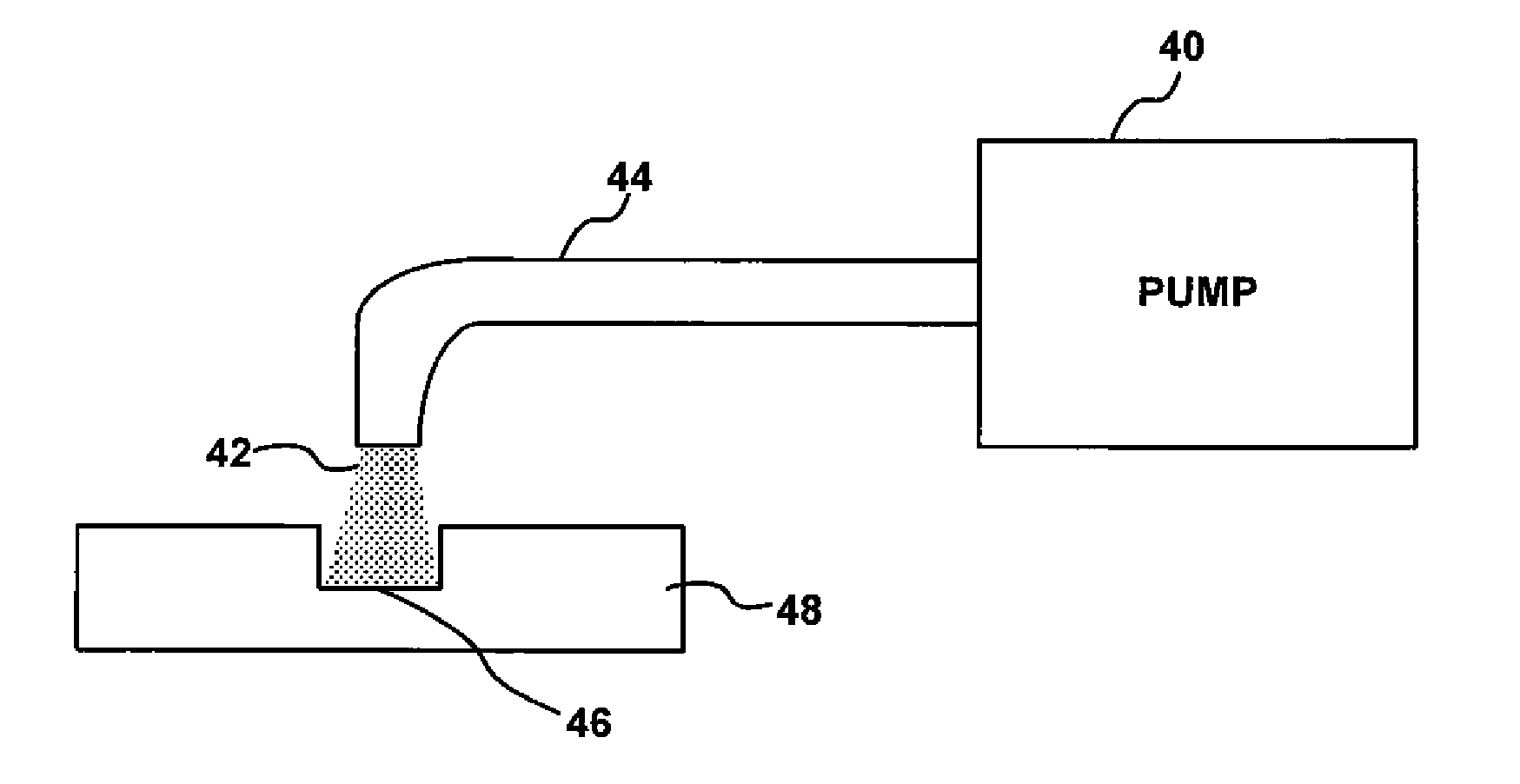
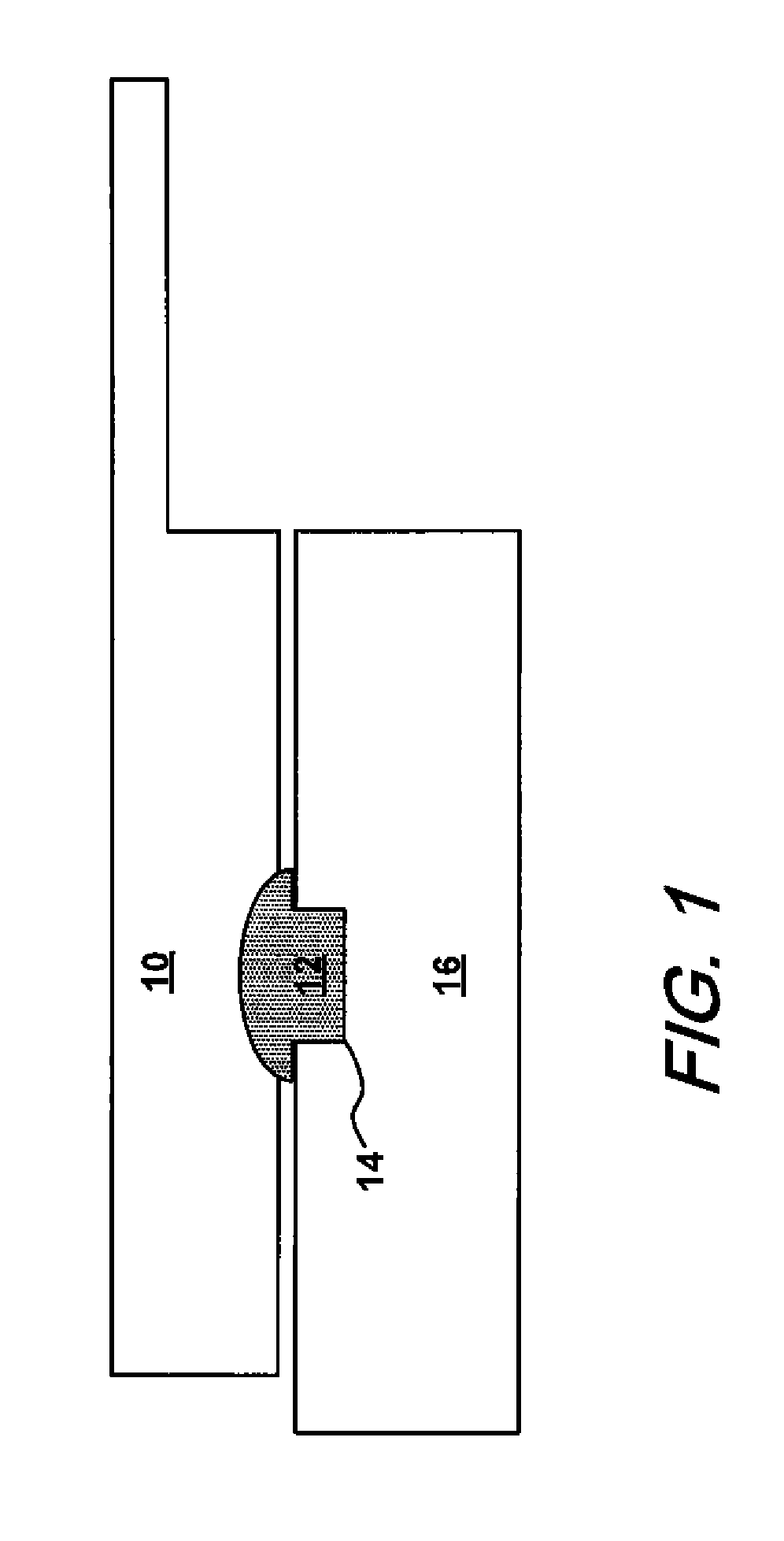
[0046]A small amount of a CL-20 slurry, prepared as described above, was taken up on a PTFE spatula and wiped over a loading hole in a fixture of an explosive device (as in FIG. 1). The mobile phase was allowed to dry. A loading hole in a second fixture was loaded with lead azide. Upon drying of the slurry mobile phase, an electrical resistance bridgewire was placed in direct contact with the lead azide and connected to the terminals of a battery. The CL-20 energetic material was successfully functioned.

example 2

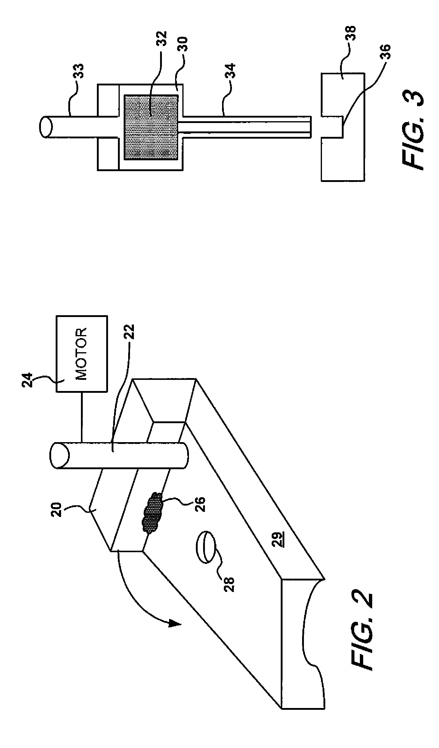
[0047]A fixture was provided comprising a plate (made of PMMA or aluminum) having a hole drilled through the plate and a trough inscribed on the plate surface so as to be in communication with the hole. CL-20 was incorporated in a slurry with ethanol, and loaded into the hole in the plate with a small volume of the slurry placed in the trough. In addition, lead azide was placed in the trough in direct contact with the CL-20 and so as to partially fill the trough. Lead styphnate was then placed in the trough to fill the remaining trough volume. An electrical resistance bridgewire was placed in direct contact with the lead azide and the bridgewire was connected to the terminals of a battery. The device was successfully functioned and, in this regard, the primary explosives, lead styphnate and lead azide, set off the CL-20 fill material, which carried out a 90° corner turn and made a dent in a lead witness plate disposed in the end of the explosive train. In a closely related example, ...

example 3

[0048]A fixture plate made of PMMA or aluminum having a hole drilled through the plate thickness was provided and the hole was loaded as in Example 1. The device was successfully functioned using a low voltage electric bridgewire, with lead azide being used as the primary initiating explosive.


PUM


Abstract

Secondary crystalline high explosives are disclosed which are suitable for filling very small volume loading holes in micro-electric initiators for micro-electro-mechanical mechanisms (MEMS), used as safe and arm (S&A) devices. The explosives are prepared by adding the such a high explosive to an aqueous first volatile mobile phase, adding such a high explosive to a non-aqueous second volatile mobile phase, mixing the first and second volatile mobile phases and then loading the combined phases into the MEMS device and allowing the aqueous and non-aqueous solvents to evaporate depositing the high explosive. Enhanced adhesion between the deposited high explosive and enhanced rheological properties can be obtained by adding a polymeric binder to both mobile phases.

Description

CROSS REFERENCE TO RELATED APPLICATIONS[0001]This application is a continuation-in-part of co-pending prior application Ser. No. 11 / 307,626 filed, Feb. 15, 2006, which in turn is a continuation-in-part of prior application Ser. No. 10 / 248,904, filed Feb. 28, 2003; the entire file wrapper contents of both prior applications are hereby incorporated herein by reference as though each is fully set forth herein; this application also claims the benefit under 35 USC §119(e) of U.S. provisional application 61 / 116,027, filed Nov. 19, 2008.FEDERAL RESEARCH STATEMENT[0002]The inventions described herein may be manufactured, used and licensed by or for the U.S. Government for U.S. Government purposes.BACKGROUND OF INVENTION[0003]1. Field of the Invention[0004]The present invention relates to a method for the precise deposition of the energetic fills that form the detonation train within ultra-miniature safety-and-arming devices used for projected munitions, and more specifically wherein the cr...

Claims


Application Information

Patent Timeline
IPC IPC(8): C06B25/00C06B25/34D03D43/00D03D23/00
CPCC06B21/0025C06B21/0033C06B45/10F42D1/10F42B33/0214F42B33/0242F42B33/0264F42B33/0207
Inventor STEC, III, DANIELWILSON, AMYFUCHS, BRIAN E.MEHTA, NEHACOOK, PAULA
Owner UNITED STATES OF AMERICA THE AS REPRESENTED BY THE SEC OF THE ARMY
Why Eureka
Try Eureka