Sensor device for measuring a magnetic field

a technology of magnetic field and sensor device, which is applied in the direction of galvano-magnetic hall-effect devices, instruments, propulsion systems, etc., can solve the problems of small space for the installation of sensors and the sensor device, and achieve the effect of improving the accuracy of the sensor, maximizing the sensor sensitivity, and reducing the cost of installation

Inactive Publication Date: 2011-06-28
SIEMENS AG
View PDF16 Cites 12 Cited by
  • Summary
  • Abstract
  • Description
  • Claims
  • Application Information

AI Technical Summary

Benefits of technology

[0019]In a further advantageous refinement of the sensor device, the means for conducting a magnetic flux is tapered in the direction of the sensor. The tapering serves to concentrate the magnetic flux and optimize sensor sensitivity. The sensor device therefore has a greater cross-sectional area in the region of the end of a tooth than in the region of the position of the sensor.
[0020]In a further advantageous refinement, the sensor can be cooled by a cooling device of the primary part. The accuracy of the sensor can be improved by means of this cooling device since the signal to noise ratio can be improved. Furthermore, more favorable sensors can be used, for example due to such a cooling measure.
[0021]The sensor device can, for example, be designed in such a way that the sensor laminate or the means for conducting a magnetic flux has the shape of a tooth of the primary part at least in one region. If the means for conducting the magnetic flux has the shape of a tooth, particularly in the region of the end of the tooth, with the shape relating particularly to the width of the tooth, it is therefore possible to ensure that the position-dependent course of the magnetic flux through the sensor device has the same shape as the useful flux of the primary part (ideally: sinusoidal). This increases the accuracy of the sensor device. One advantage of the sensor device according to the invention is its low space requirement. A further advantage is that incorrect mounting of the sensor device or of the sensor, for example by a customer, can be precluded by, in particular complete, integration in the primary part. The integration is the result, for example, of the fact that the sensor device is already connected to the primary part during production of said primary part. The sensor device can also be encapsulated with the primary part of the linear motor. In a further advantageous refinement, the sensor device is a fixed constituent part of the primary part, with the sensor of the sensor device being exchangeable, for example in the event of a defect.

Problems solved by technology

The reason for this is, in particular, the compactness of the sensor device.
In torque motors, there is, for example, little space for the installation of sensors.

Method used


Image

  • Sensor device for measuring a magnetic field
  • Sensor device for measuring a magnetic field
  • Sensor device for measuring a magnetic field

Examples


Embodiment Construction

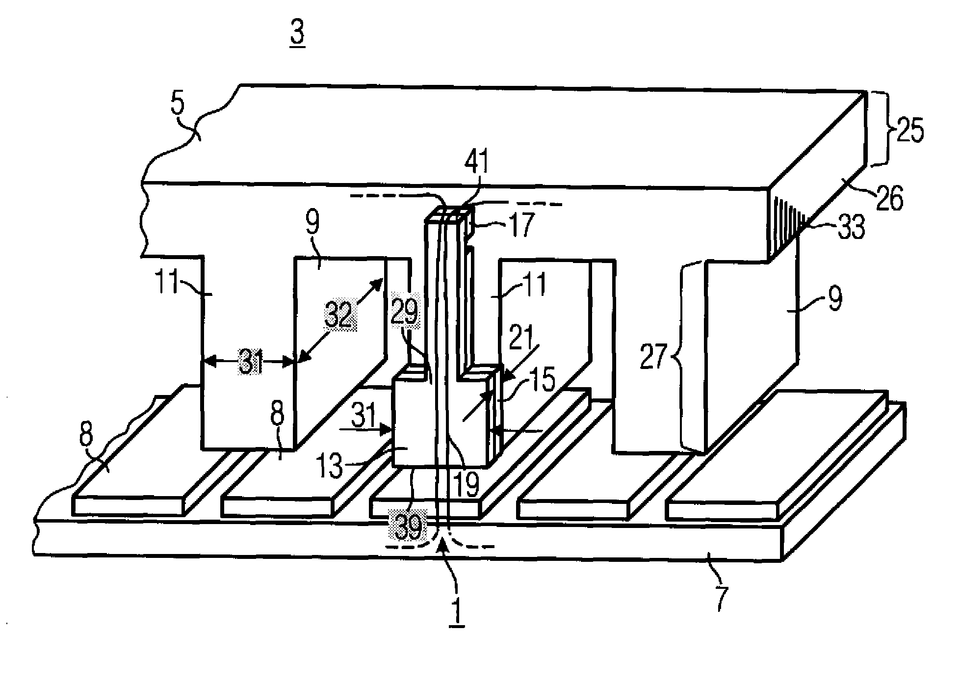
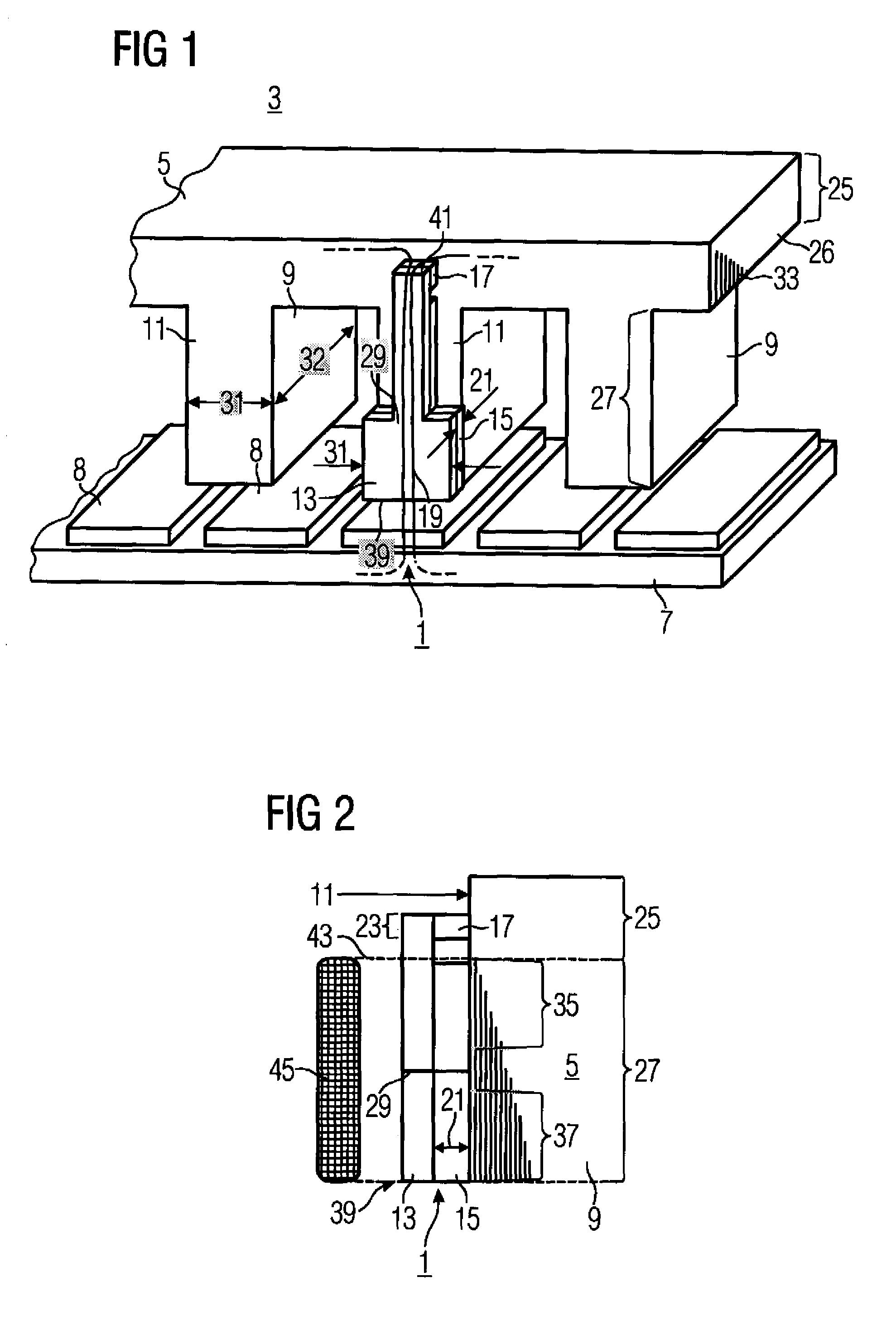
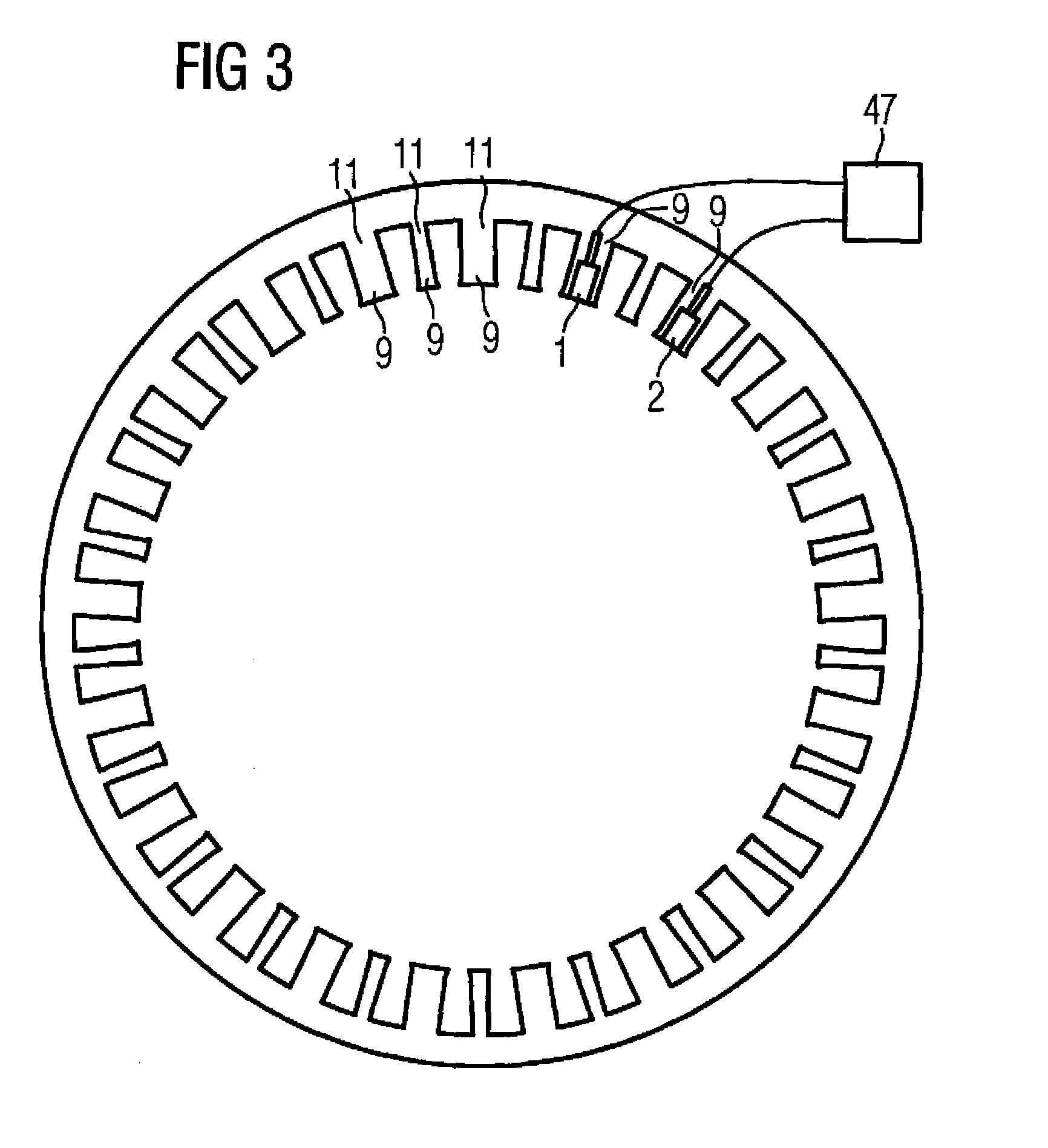
[0036]The illustration of FIG. 1 shows an electrical machine 3. The electrical machine 3 is a linear motor. The electrical machine 3 has a primary part 5 and a secondary part 7. The secondary part 7 has permanent magnets 8. The primary part 5 is laminated, with a plurality of laminates being positioned one behind the other in order to form the laminate arrangement 33. The primary part 5 also has a back 26 and teeth 9. The teeth 9 have a tooth width 31 and a tooth length 32. A flank 11 is formed in the region in which a laminate adjoins the laminate arrangement of the primary part 5. A sensor device 1 is positioned on the flank 11. The sensor device 1 is therefore positioned on the side of a primary part 5. The sensor device 1 is designed in a layered manner. The sensor device 1 has a sensor laminate 13. The sensor laminate 13 is at a distance from the flank 11. A distance 21 is created by means of a spacer 15. The sensor laminate 13 has a first end 39 and a second end 41. The first ...


PUM


Abstract

A sensor device for measuring a magnetic field in the region of a primary part of a permanently excited electrical machine or a corresponding primary part having teeth includes a sensor metal plate for conducting a magnetic field, a spacer, and a sensor for measuring a magnetic field. A distance between the sensor metal plate and a flank of a tooth of the primary part can be created by the spacer. The sensor may be a Hall sensor and is arranged in a region of the sensor metal plate between the sensor metal plate and the primary part.

Description

CROSS-REFERENCES TO RELATED APPLICATIONS[0001]This application is the U.S. National Stage of International Application No. PCT / EP2005 / 054601, filed Sep. 16, 2005, which designated the United States and has been published as International Publication No. WO 2006 / 040235 and which claims the priority of German Patent Application, Serial No. 10 2004 045 934.7, filed Sep. 22, 2004, pursuant to 35 U.S.C. 119(a)-(d).[0002]The invention relates to a sensor device and to a primary part with a sensor device, it being possible to use the sensor device for measuring a magnetic field or a magnetic flux.BACKGROUND OF THE INVENTION[0003]In an electrical machine, for example a linear motor or a torque motor, where the electrical machine has a primary part or a secondary part, it is necessary to use an encoder or a corresponding sensor in order to determine the position of the primary part with respect to the secondary part. The electrical machine is, for example, a permanently excited synchronous m...

Claims


Application Information

Patent Timeline
Patent Type & Authority Patents(United States)
IPC IPC(8): G01B7/14G01B7/30
CPCH02K41/031H02K11/0021H02K29/08H02K11/215
Inventor JAJTIC, ZELJKOMATSCHEKO, GERHARDSCHIELE, STEFAN
Owner SIEMENS AG
Why Eureka
Try Eureka