
Systems and methods for detection of VT and VF from remote sensing electrodes

a technology of remote sensing electrodes and detection methods, applied in the field of rwave detection, can solve the problems of life-threatening, rapid deterioration to ventricular fibrillation, and inability to effectively pump blood, and achieve the effect of high myopotential levels

Active Publication Date: 2011-06-28
PACESETTER INC
View PDF38 Cites 17 Cited by
  • Summary
  • Abstract
  • Description
  • Claims
  • Application Information

AI Technical Summary

Benefits of technology

[0008]Embodiments of the present invention are also directed to methods and systems for performing ventricular arrhythmia monitoring using at least two sensing channels that are each associated with a different pair of extracardiac remote sensing electrodes. In accordance with an embodiment, myopotential associated with at least two sensing channels is monitored, and then a ventricular arrhythmia monitoring mode is selected based on the monitored myopotential. Ventricular arrhythmia monitoring modes include, for example, a single channel sensing mode and a dual channel sensing mode. Ventricular arrhythmia monitoring is then performed using the selected monitoring mode. In accordance with an embodiment of the pr

Problems solved by technology

Some are harmless, but others are life threatening in that they can quickly deteriorate to a ventricular fibrillation.
When the ventricles fibrillate, they do not contract normally, so they cannot effectively pump blood.
VF quickly becomes more erratic, resulting in sudden cardiac arrest.
Appropriate detection of ventricular arrhythmias (requiring high voltage therapy) and discrimination of supraventricular arrhythmias (not requiring high voltage therapy) in a noisy signal is challenging and of great importance, particularly as it relates to an implanted defibrillator using subcutaneous extracardiac electrodes or an external defibrillator.

Method used


Image

  • Systems and methods for detection of VT and VF from remote sensing electrodes
  • Systems and methods for detection of VT and VF from remote sensing electrodes
  • Systems and methods for detection of VT and VF from remote sensing electrodes

Examples


Embodiment Construction

[0024]The following description is of the best modes presently contemplated for practicing various embodiments of the present invention. This description is not to be taken in a limiting sense but is made merely for the purpose of describing the general principles of the invention. The scope of the invention should be ascertained with reference to the issued claims. In the description of the invention that follows, like numerals or reference designators will be used to refer to like parts or elements throughout.

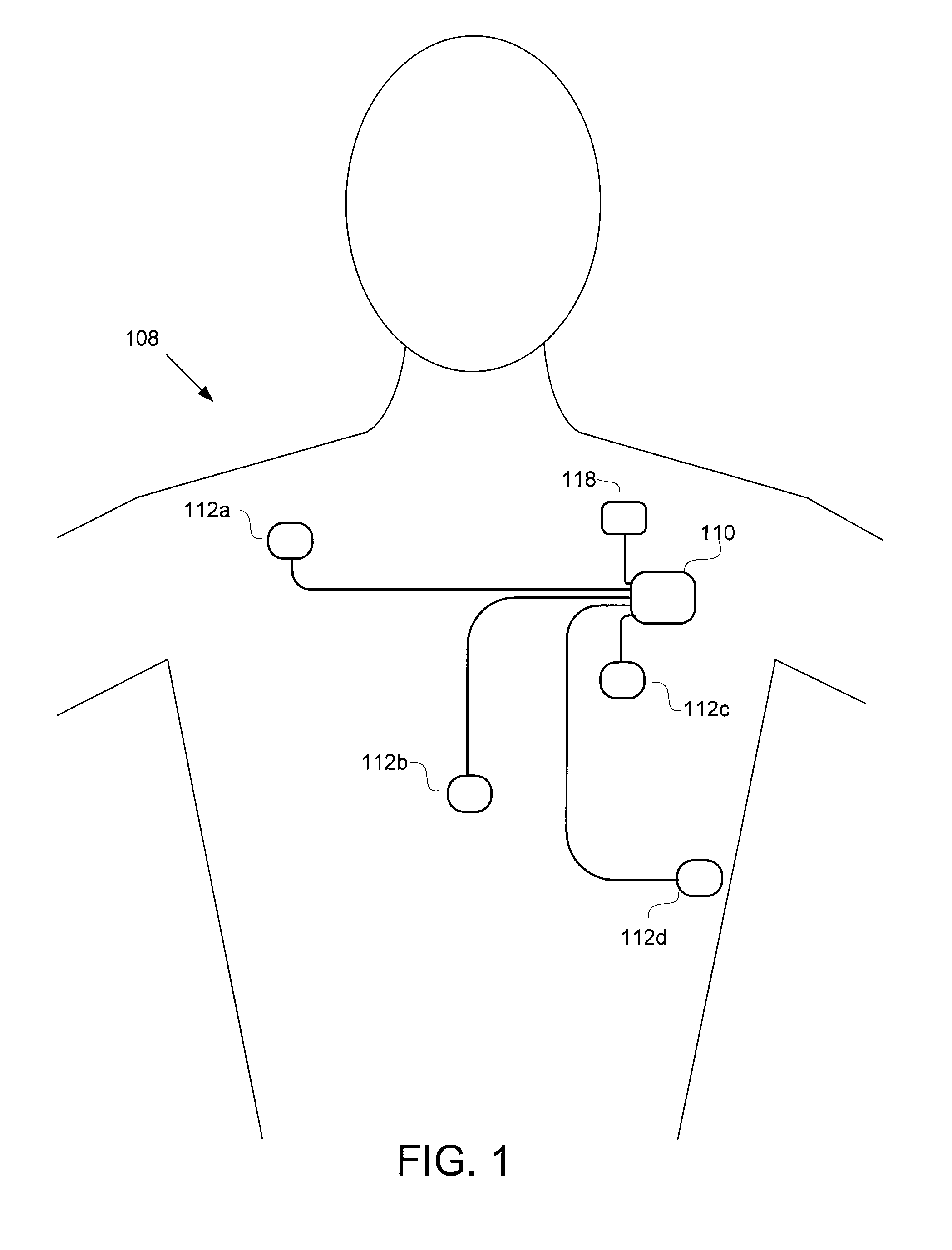
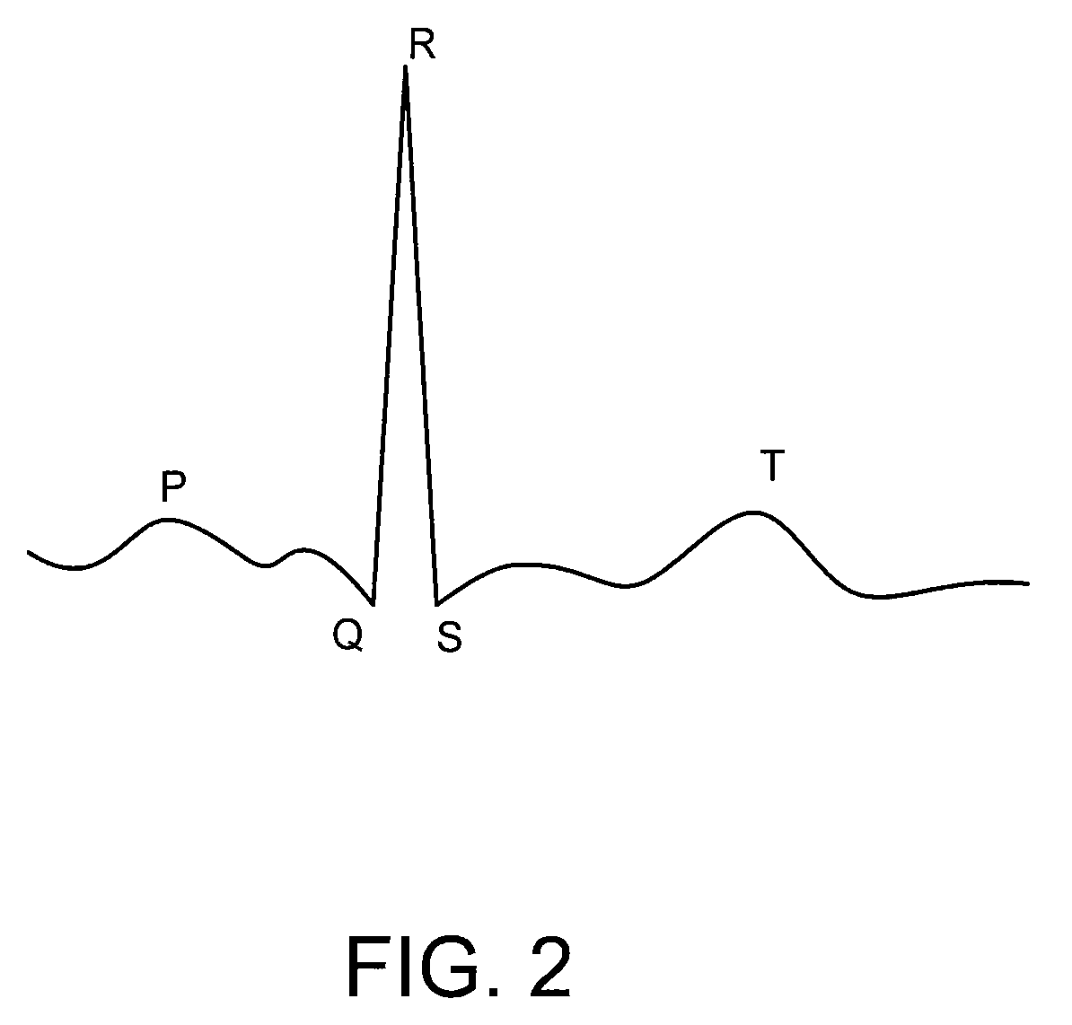
[0025]Before going into specific details regarding the various embodiments of the present invention, it is first useful to describe an exemplary extracardiac / extravascular defibrillation system, and an exemplary ECG signal.

Overview of Extracardiac / Extravascular Defibrillation System

[0026]Referring first to FIG. 1, an exemplary extracardiac defibrillation system 108 includes a subcutaneous (subQ) stimulation device 110 and multiple subQ extracardiac electrodes 112 (also referr...


PUM


Abstract

Methods and systems are provided for performing ventricular arrhythmia monitoring using at least two sensing channels that are each associated with different sensing vectors, for example by different pairs of extracardiac remote sensing electrodes. Myopotential associated with each of the sensing channels in monitored, and a ventricular arrhythmia monitoring mode is selected based thereon (e.g., based on determined myopotential levels). Ventricular arrhythmia monitoring is then performed using the selected monitoring mode.

Description

CROSS-REFERENCE TO RELATED APPLICATIONS[0001]This application is a continuation of U.S. patent application Ser. No. 10 / 998,027, filed Nov. 24, 2004, titled “Systems and Methods for Detection of VT and VF from Remote Sensing Electrodes,” now U.S. Pat. No. 7,447,540, which is related to U.S. patent application Ser. No. 10 / 998,026, filed Nov. 24, 2004, titled “Systems and Methods for Detection of VT and VF from Remote Sensing Electrodes”, now U.S. Pat. No. 7,403,813.FIELD OF THE INVENTION[0002]Embodiments of present invention relate to detecting R-waves, monitoring myopotential, detecting levels of myopotential, as well as detecting and treating cardiac arrhythmias.BACKGROUND[0003]Ventricular arrhythmias include ventricular tachycardia (VT) and ventricular fibrillation (VF). A tachycardia is a fast heart rate (usually over 100 beats per minute) typically caused by disease or injury. It can also be part of a normal response to increased activity or oxygen demands. The average heart beat...

Claims


Application Information

Patent Timeline
IPC IPC(8): A61N1/00A61B5/352
CPCA61B5/04011A61B5/046A61N1/3956A61N1/3702A61B5/0464A61B5/341A61B5/361A61B5/363
Inventor NABUTOVSKY, YELENAFARAZI, TARANEH GHAFFARIBJORLING, ANDERSNOREN, KJELLBORNZIN, GENE A.
Owner PACESETTER INC
Learn More